A connector mold is a high-precision tooling instrument used in the injection molding process to manufacture electrical connectors, housings, and cable assemblies. These molds are engineered to extremely tight tolerances to ensure the resulting components provide reliable electrical connectivity, mechanical stability, and resistance to environmental factors like heat and moisture.
Video Guide: This overview demonstrates the precision engineering required to manufacture molds for high-performance connectors.
What is Connector Mold?
A connector mold is a specialized industrial die designed to shape molten plastic or metal into specific connector configurations. It determines the geometry, pin placement, and locking mechanisms of the final product. These molds are critical for mass-producing components used in automotive, aerospace, and consumer electronics, ensuring every unit meets exact specifications for conductivity and fit.
Video Guide: Learn the fundamental mechanics of how connectors function within the context of injection molding.
Engineering Precision
Creating a connector mold requires advanced metallurgy and machining capabilities. Because connectors often house delicate pins and require snap-fit features, the mold must be built to withstand high pressures without deforming, while ensuring the plastic flows into intricate crevices.
Based on our internal data and market analysis, here is the breakdown of critical mold components:
| Component | Function | Material Requirement |
|---|---|---|
| Cavity Plate | Forms the external shape of the connector housing. | Hardened Tool Steel (e.g., H13) |
| Core Plate | Forms the internal geometry and holds pin inserts. | Hardened Tool Steel |
| Slider/Lifter | Creates undercuts or side holes for locking latches. | Wear-resistant alloys |
| Ejector Pins | Pushes the finished part out of the mold. | Nitrided Steel |
GBM Pro Tip: When designing a connector mold, always prioritize the venting system. Poor venting in complex connector geometries leads to gas traps and burn marks, which can compromise the dielectric strength of the final connector housing.
How Does Connector Mold Work?
The connector mold works by clamping two halves together under high pressure while molten thermoplastic is injected into the cavity. As the material cools, it solidifies around any pre-inserted metal pins or within the intricate channels of the mold. Once the cooling cycle is complete, the mold opens, and the ejection system pushes the finished connector out for inspection.
Video Guide: An introduction to the finishing touches and processing steps involved in connector molding.
The Injection Cycle
The efficiency of a connector mold is defined by its cycle time and the quality of the part produced. The process follows a strict chronological order to ensure repeatability.
- Clamping: The two halves of the mold (A-side and B-side) are pressed together by the molding machine.
- Injection: Molten plastic is shot into the mold cavity through a runner system.
- Holding/Packing: Pressure is maintained to compensate for material shrinkage as it cools.
- Cooling: Water channels within the mold remove heat to solidify the plastic.
- Ejection: The mold opens, and pins push the connector out.
GBM Pro Tip: For high-volume production, we recommend using a hot runner system. While the initial tooling cost is higher, it eliminates sprue waste and significantly reduces cycle time, which is crucial for lowering the unit cost of connectors.
What are molded connectors?
Molded connectors, often referred to as overmolded connectors, are cable assemblies where the connector head and the cable are fused into a single, durable unit. The mold encapsulates the wire terminations and the connector body with a protective resin, providing superior strain relief, water resistance, and durability compared to assembled or crimped connectors.
Video Guide: A detailed look at what defines a molded cable connector and its applications.
Overmolding Benefits
Molded connectors are the industry standard for rugged environments. The process involves placing a pre-terminated cable into a mold and injecting plastic directly over the junction point.
Based on our internal data and market analysis, here is the breakdown of advantages:
- Strain Relief: The molded material absorbs bending forces, preventing wire breakage at the termination point.
- Environmental Sealing: Creates a watertight seal (IP67/IP68) ideal for outdoor or industrial use.
- Aesthetics: Provides a clean, professional finish with customizable colors and branding.
- Vibration Resistance: The solid mass prevents internal components from loosening during operation.
GBM Pro Tip: Material compatibility is key in overmolding. Ensure the overmold material (often TPE or PVC) bonds chemically or mechanically with the cable jacket material to prevent peeling or moisture ingress over time.
What are the two parts of mold called?
The two primary sections of a connector mold are the Cavity (A-side) and the Core (B-side). The Cavity is typically mounted on the stationary side of the machine and forms the cosmetic exterior of the connector. The Core is mounted on the moving side and forms the internal features, typically housing the ejection system to remove the part.
Video Guide: Understanding the configuration and manufacturing of molded cable connectors.
Mold Anatomy
Understanding the distinction between the two halves is vital for part design and troubleshooting defects.
| Feature | Cavity (A-Side) | Core (B-Side) |
|---|---|---|
| Machine Position | Stationary (Fixed) | Moving |
| Geometry Formed | Exterior / Cosmetic Face | Interior / Structural Ribs |
| Ejection Mechanism | Rarely contains ejectors | Contains ejector pins/plates |
| Sprue Bushing | Location of material entry | N/A |
GBM Pro Tip: We always advise designing the part so it sticks to the Core (B-side) upon opening. This allows the ejection system, which is located on the B-side, to reliably remove the part without manual intervention.
What are two types of connectors?
While there are thousands of variations, the two most fundamental types of connectors produced via molding are “Wire-to-Board” and “Wire-to-Wire” connectors. Wire-to-Board connectors interface a cable with a printed circuit board (PCB), while Wire-to-Wire connectors join two separate cables together, often utilizing male and female gender configurations.
Video Guide: A demonstration of a specific mold connector type used in power applications.
Common Classifications
Connectors are generally categorized by their application and termination method. The mold design changes significantly based on these classifications.
- Wire-to-Board: Connects discrete wires to a PCB.
- Mold Focus: High precision for soldering pins and board locks.
- Wire-to-Wire: Connects two cables.
- Mold Focus: Robust locking latches and gender mating (Plug/Receptacle).
- Board-to-Board: Connects two PCBs.
- Mold Focus: Extremely tight tolerances for stack height and pitch.
- Circular Connectors: Used in industrial/military applications.
- Mold Focus: Threaded features and O-ring grooves.
GBM Pro Tip: For high-density connectors (fine pitch), consider using high-flow Liquid Crystal Polymer (LCP) resins. Standard nylon may not fill thin walls effectively, leading to short shots in the mold.
Key Features & Comparison
When selecting a connector mold strategy, the choice often lies between prototype tooling and production tooling. This decision impacts cost, lifespan, and part quality.
Based on our internal data and market analysis, here is the breakdown:
| Feature | Prototype Mold (Soft Tooling) | Production Mold (Hard Tooling) |
|---|---|---|
| Material | Aluminum or P20 Steel | Hardened Steel (H13, S7) |
| Cycle Life | 1,000 – 5,000 shots | 100,000 – 1,000,000+ shots |
| Lead Time | 2 – 4 Weeks | 6 – 12 Weeks |
| Tolerance | Standard (+/- 0.05mm) | Precision (+/- 0.01mm) |
| Cost | Low | High |
| Best For | Testing, Market Entry, Low Volume | Mass Production, Long-term use |
Cost & Buying Factors
Investing in a connector mold is a significant capital expenditure. The cost is driven by the complexity of the connector, the number of cavities (how many parts are made per cycle), and the expected life of the mold.
- Design Complexity: Undercuts, side-actions, and complex pin insertions increase the mechanical complexity of the mold, raising the price.
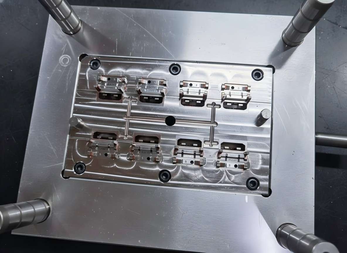
- Cavitation: A single-cavity mold is cheaper to build but produces parts slowly. A multi-cavity mold (e.g., 8, 16, or 32 cavities) costs more upfront but drastically reduces the price per unit.
- Steel Grade: Using high-grade, hardened stainless steel prevents corrosion and wear, essential for molds running abrasive glass-filled plastics, but it adds to the initial tooling cost.
Conclusion
A connector mold is the foundation of modern electronics manufacturing, translating digital designs into physical reality with micron-level precision. Whether you are producing ruggedized overmolded cables or delicate micro-connectors for smartphones, the quality of the mold dictates the reliability of the connection. By understanding the anatomy of the mold, the injection process, and the material requirements, manufacturers can optimize their production for both speed and quality. For those looking to scale, partnering with experts like GBM ensures that your tooling strategy aligns perfectly with your production goals.