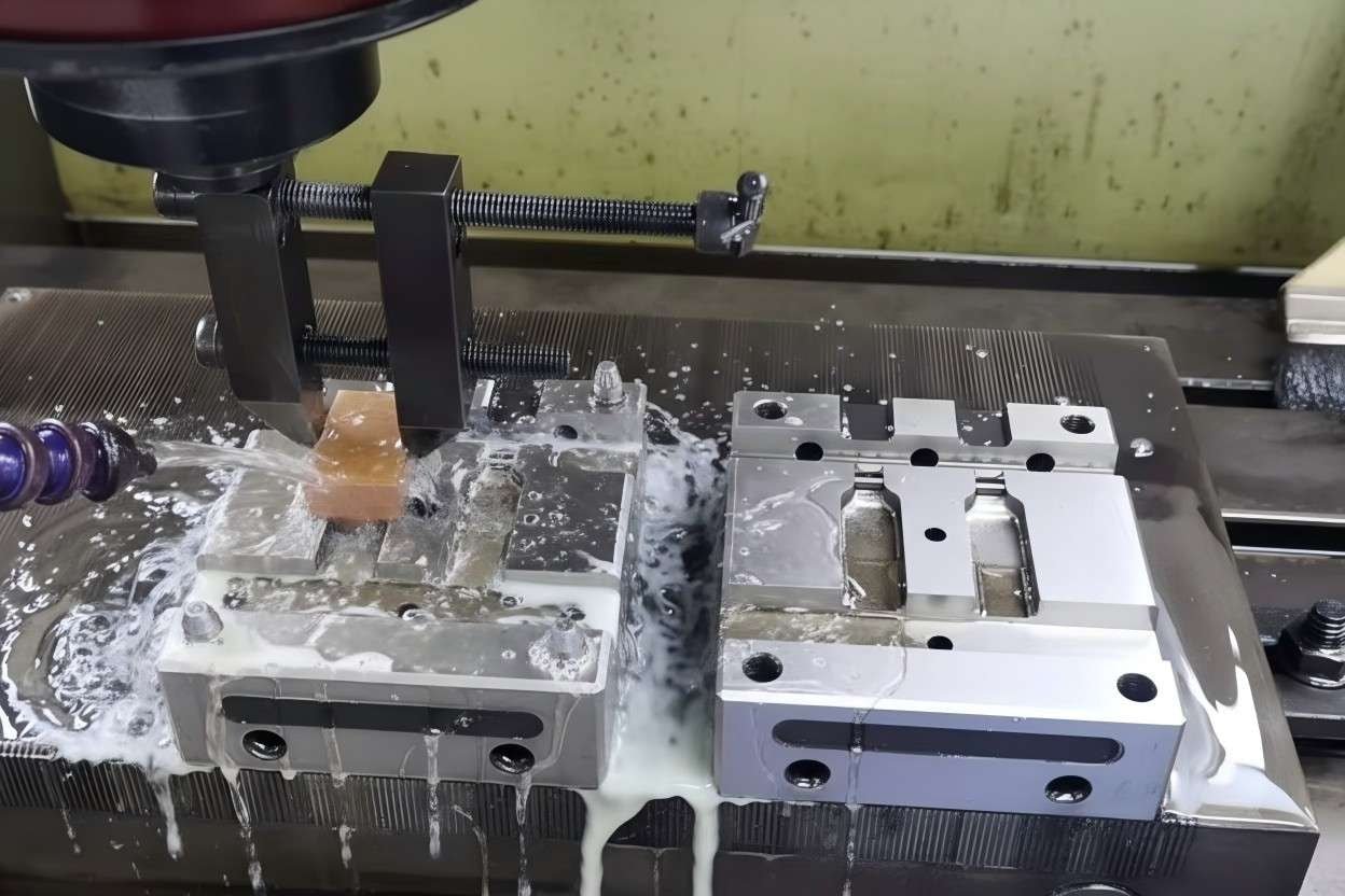
The process of connector mold manufacturing involves a highly precise sequence of engineering design, CNC machining, EDM (Electrical Discharge Molding), and assembly to create the tooling required for mass-producing electronic connectors. This critical manufacturing stage dictates the dimensional accuracy, electrical performance, and mechanical durability of the final connector product used in industries ranging from automotive to consumer electronics. At GBM, we emphasize that the quality of the mold directly correlates to the reliability of the connection interface.
Video Guide: This video demonstrates the precision engineering required to manufacture high-quality molds for electronic connectors.
What is Connector Mold?
A connector mold is a specialized precision tool, typically made from hardened steel, used in the injection molding process to form plastic housings or encapsulate metal terminals for electronic connectors. It serves as the negative impression of the final product, defining the complex geometries, pin spacing (pitch), and locking mechanisms required for signal and power transmission.
Video Guide: An overview of the plastic design process and considerations for creating effective connector molds.
Understanding the Tooling Anatomy
The connector mold is not a single block of metal but a complex assembly of precision components. High-performance connectors often require molds with tolerances as tight as ±0.005mm to ensure that pins align correctly with the mating part.
Based on our internal data and market analysis, here is the breakdown of core components:
- Mold Base: The rigid steel frame that holds all internal components together and mounts to the injection molding machine.
- Cavity and Core: The cavity forms the external shape (housing), while the core forms the internal features.
- Slider/Side Actions: Mechanical devices used to create undercuts or locking features that cannot be formed by the simple opening and closing of the mold.
- Ejector Pins: Steel pins that push the finished connector out of the mold once the plastic has solidified.
- Inserts: Replaceable steel sections that allow for different pin configurations within the same main mold base.
GBM Pro Tip: When designing a connector mold, always prioritize high-grade tool steel (like S136 or H13) for the cavity and core. While softer steels are cheaper upfront, high-grade steel withstands the abrasive nature of glass-filled plastics (like LCP or PBT) used in connectors, ensuring millions of cycles without dimensional drift.
How Does Connector Mold Work?
The connector mold works by clamping together under high pressure to create a sealed volume, into which molten thermoplastic is injected at high speed. The mold holds the plastic in the shape of the connector housing while it cools and solidifies, often around pre-inserted metal contacts (insert molding), before opening to eject the finished part.
Video Guide: A mechanical breakdown explaining the role of the connector within the injection molding cycle.
The Injection Mechanism
The working principle relies on precise thermal and pressure management. If the mold is too cold, the plastic may not fill thin walls (short shots); if it is too hot, the cycle time increases, and warping may occur.
- Clamping: The two halves of the mold (A-side and B-side) are pressed together with tons of force to resist the pressure of injection.
- Injection: Molten plastic is forced through the sprue and runners into the mold cavity.
- Holding/Packing: Additional pressure is applied to pack more material into the cavity to compensate for shrinkage as the plastic cools.
- Cooling: Water channels inside the mold remove heat, solidifying the plastic.
- Ejection: The mold opens, and ejector pins push the connector off the core.
GBM Pro Tip: For connectors with long, thin pins, we recommend using a balanced runner system in the mold. This ensures that the pressure of the entering plastic does not bend or displace the metal pins (pin wash), which is a common failure mode in connector molding.
What are the 4 stages of injection molding?
The four distinct stages of the injection molding process for connectors are Clamping, Injection, Cooling, and Ejection. Each stage must be optimized to prevent defects; for example, the cooling phase typically consumes the majority of the cycle time and determines the crystalline structure of the polymer.
Video Guide: Watch an all-electric injection machine produce electronic connectors through the four-stage cycle.
Detailed Process Breakdown
Optimizing these four stages is essential for reducing unit costs and maintaining high throughput at GBM.
- Stage 1: Clamping:
- The mold halves are closed.
- Tonnage force is applied (e.g., 50 to 500 tons depending on connector size).
- Stage 2: Injection:
- Screw advances, pushing melt into the mold.
- Key Metric: Injection speed affects the surface finish and flash formation.
- Stage 3: Cooling:
- The part creates its shape stability.
- Constraint: Wall thickness dictates cooling time; thicker walls take longer to cool.
- Stage 4: Ejection:
- Mold opens.
- Robotic arms or gravity remove the part.
- Cycle resets.
GBM Pro Tip: The “Cooling” stage is where money is made or lost. We utilize conformal cooling channels—water lines that curve to follow the shape of the connector—to reduce cooling time by up to 20% compared to standard straight-line cooling channels.
How much does it cost to have an injection mold made?
The cost of a connector injection mold ranges significantly from $3,000 for a simple, single-cavity prototype mold to over $100,000 for a high-precision, multi-cavity production mold. The price is driven by the complexity of the connector design, the number of cavities (output capacity), and the grade of steel used.
Video Guide: This video details the finishing touches and precision required in mold making, which are primary cost drivers.
Cost Drivers in Mold Making
The initial investment in a mold is high, but the per-unit cost drops as volume increases.
Based on our internal data and market analysis, here is the breakdown:
| Cost Factor | Low Cost ($3k – $10k) | High Cost ($20k – $100k+) |
|---|---|---|
| Cavitation | Single Cavity (1 part per cycle) | Multi-Cavity (8, 16, or 32 parts per cycle) |
| Steel Grade | P20 or Aluminum (Softer) | Hardened S136 or H13 (High durability) |
| Lifespan | < 50,000 shots | > 1,000,000 shots |
| Complexity | Simple open/shut mechanism | Complex slides, lifters, and unscrewing mechanisms |
| Tolerances | Standard (±0.1mm) | Precision (±0.005mm) |
GBM Pro Tip: Do not over-specify the mold life if you are validating a new product. Start with a “soft mold” (P20 steel) for the first 10,000 units. Once the design is market-proven, invest in a Class A hardened steel mold for mass production to save upfront capital.
What are molded connectors?
Molded connectors, often referred to as overmolded connectors, are cable assemblies where the connector head and the cable strain relief are fused into a single solid piece using injection molding. This process creates a robust, watertight seal that is far more durable than mechanical snap-together housings.
Video Guide: A clear explanation of what molded cable connectors are and their advantages.
Types of Molded Connectors
Molded connectors are ubiquitous in rugged environments and consumer electronics (like USB cables).
- Insert Molded: Metal pins or terminals are placed into the mold first, and plastic is injected around them. This creates a hermetic seal around the pins.
- Overmolded Cable Assemblies: A pre-terminated cable is placed in a mold, and a resin (like PVC or TPE) is injected over the termination point to create a handle and strain relief.
- Two-Shot Molded: Uses two different plastics (e.g., hard ABS for structure and soft TPE for grip) injected in the same cycle.
GBM Pro Tip: For outdoor applications, always choose overmolded connectors. The molding process fills the gaps between wires and terminals, preventing moisture ingress and oxidation, which are the leading causes of failure in non-molded connectors.
Key Features & Comparison
When selecting a manufacturing process for connectors, it is vital to understand the difference between standard assembly and molded solutions.
Based on our internal data and market analysis, here is the breakdown:
| Feature | Assembled Connector (Snap-on) | Molded Connector (Overmolded) |
|---|---|---|
| Durability | Moderate; parts can separate under stress. | High; fused into a single unit. |
| Water Resistance | Low; requires gaskets/O-rings. | High; naturally sealed by plastic. |
| Strain Relief | Mechanical clamp (often weak). | Chemical/Thermal bond (very strong). |
| Aesthetics | Visible seams and screws. | Smooth, seamless finish. |
| Tooling Cost | Low (standard parts). | High (requires custom mold). |
| Repairability | Can be opened and repaired. | Permanent; cannot be repaired. |
Cost & Buying Factors
When sourcing connector molds or molded connectors, consider the total cost of ownership rather than just the tooling price.
- Resin Selection: Engineering plastics like LCP (Liquid Crystal Polymer) are expensive but necessary for high-temperature reflow soldering. Using cheap PVC for internal connectors will lead to melting during assembly.
- Cycle Time: A mold with more cavities costs more but produces parts faster, lowering the piece price. If you need 1 million units, a 4-cavity mold is actually “more expensive” in the long run than a 16-cavity mold due to machine time costs.
- Maintenance: Molds require regular cleaning and pin replacement. Ensure your supplier includes a maintenance schedule in the contract.
GBM Pro Tip: Always request a “Mold Flow Analysis” before cutting steel. This software simulation predicts how the plastic will flow, revealing potential air traps or weld lines that could weaken the connector. Fixing these issues digitally is free; fixing them in steel is expensive.
Conclusion
The process of connector mold manufacturing is a blend of precision metallurgy and polymer science. From the initial design of the cavity and core to the four stages of injection molding, every step influences the final connectivity and durability of the electronic device. Whether utilizing insert molding for hermetic seals or overmolding for rugged cable assemblies, the quality of the mold is paramount.
At GBM, we understand that a connector is only as good as the mold it came from. By balancing tooling costs with production volume and selecting the correct steel and resin, manufacturers can ensure high-performance connectivity that withstands the rigors of the real world.