Designing parts for plastic manufacturing requires a deep understanding of material behaviors, tooling constraints, and process dynamics. This comprehensive guide provides engineers with the essential principles needed to optimize components for manufacturability, reduce tooling costs, and eliminate common defects. By applying these proven design for manufacturability (DFM) strategies, you can transition seamlessly from prototyping to high-volume production while maintaining strict quality standards.
What is injection molding?
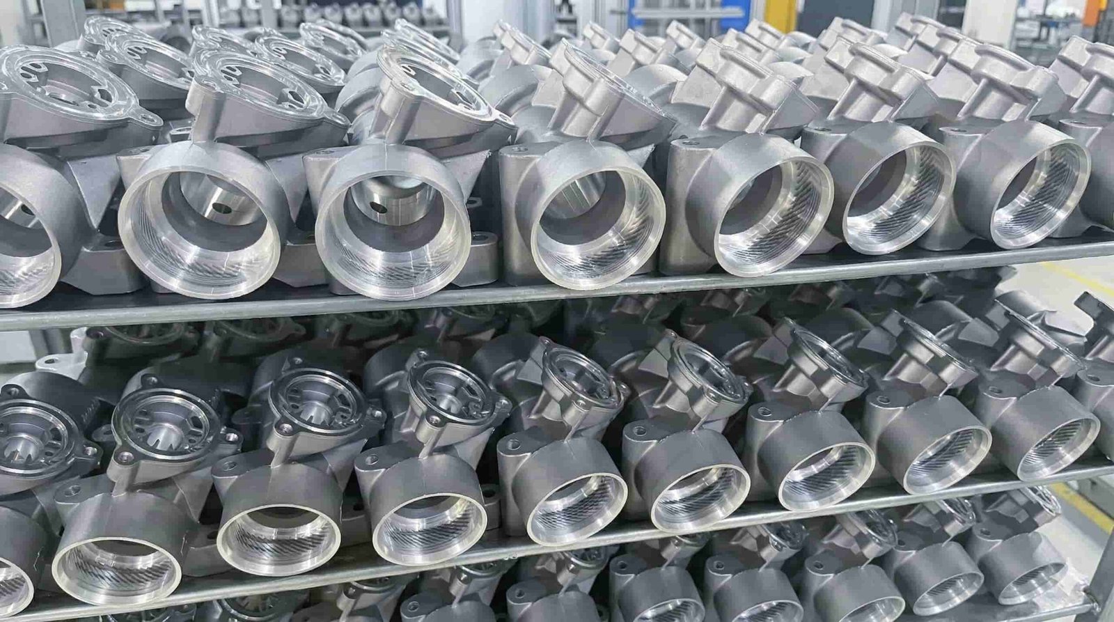
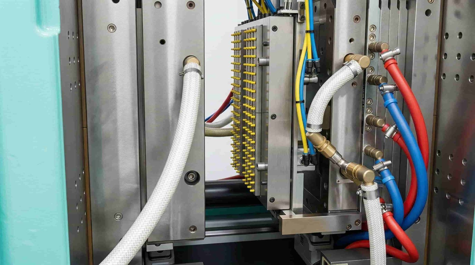
Injection molding is a highly efficient manufacturing process used to produce identical plastic parts in large volumes. It involves melting plastic pellets and injecting them under high pressure into a precisely machined metal mold cavity, where the material cools and solidifies into the final desired shape.
Core Manufacturing Process
The technology relies on a combination of thermodynamics, fluid dynamics, and mechanical engineering to transform raw polymers into finished goods. Understanding the basic mechanics is the first step toward designing better parts.
- Plastication: Raw thermoplastic pellets are fed via a hopper into a heated barrel containing a reciprocating screw.
- Injection: The screw pushes the molten plastic forward, forcing it through a nozzle, sprue, and runner system into the mold cavity.
- Cooling: Coolant channels within the steel or aluminum mold remove heat from the plastic, causing it to freeze into its solid form.
- Ejection: The mold halves separate, and ejector pins push the finished component out of the tool.
GBM Pro Tip: Always design with a uniform wall thickness to prevent sink marks and warping. Variations in thickness cause uneven cooling rates, which is the leading cause of dimensional instability in molded parts.
How Does injection molding Work?
The process operates on a continuous, highly automated cycle of clamping, injection, cooling, and ejection. Granular thermoplastic is sheared by a rotating screw to reach a molten state, forced into a clamped mold under immense pressure, and held until rigid enough for safe removal.
The Molding Cycle Breakdown
To design effectively for this manufacturing method, engineers must understand how the machinery cycles through each phase, as every second added to the cycle time increases the final part cost.
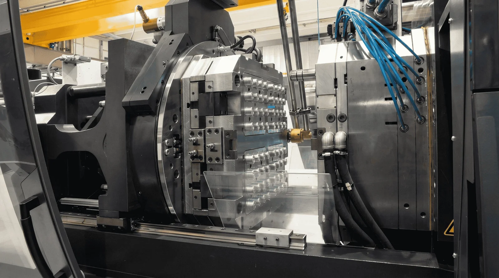
- Clamping Phase: The two halves of the mold are securely closed by the clamping unit. Sufficient clamping force is applied to keep the mold shut against the high pressure of the injected plastic.
- Injection Phase: The molten plastic is rapidly injected into the cavity. The pressure is maintained (packing phase) to compensate for material shrinkage as it cools.
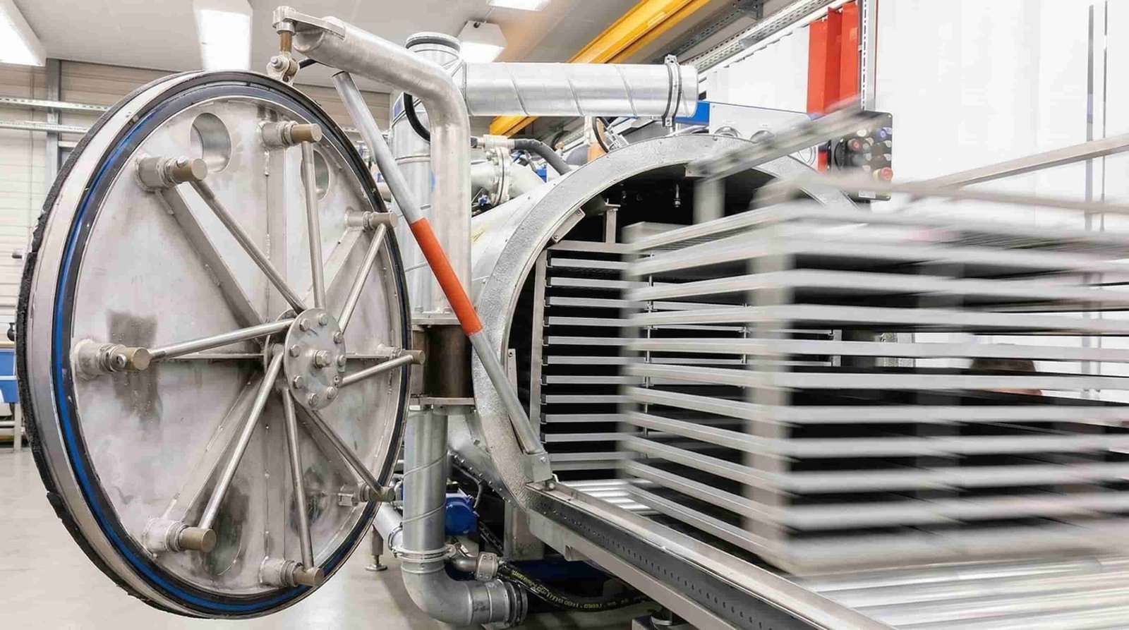
- Cooling Phase: The plastic begins to cool the moment it touches the interior mold surfaces. The part must remain in the mold until it is structurally rigid.
- Ejection Phase: The clamping unit opens the mold, and an automated mechanism pushes the part off the core, preparing the machine for the next cycle.
GBM Pro Tip: Pay close attention to your gate placement. The gate should always be located at the thickest section of the part to ensure proper packing and minimize flow marks during the high-pressure injection phase.
What CAD software is used for injection molding?
Engineers primarily use advanced 3D CAD software like SolidWorks, Autodesk Inventor, PTC Creo, and Siemens NX for injection molding design. These platforms offer specialized tooling modules and mold flow simulation capabilities to accurately predict how molten plastic will fill the mold cavity.
🎥 Mastering CAD for Molding: Watch our engineering breakdown of the most common design flaws—like inadequate draft and uneven walls—and learn how to fix them before cutting steel.
Industry Standard Design Tools
Selecting the right CAD package is vital for analyzing draft angles, wall thicknesses, and potential tooling interferences before any steel is cut.
Choosing the right CAD package is vital. Here is a comparison of industry-standard platforms used for DFM validation:
| CAD Software | Key Molding Features | Best Use Case |
|---|---|---|
| SolidWorks | Plastics simulation, draft analysis, mold tools | General mechanical design and DFM validation |
| PTC Creo | Advanced surfacing, tooling design extension | Complex geometries and high-precision tooling |
| Siemens NX | Mold Wizard, comprehensive flow analysis | Enterprise-level automotive and aerospace parts |
| Autodesk Fusion 360 | Cloud-based collaboration, integrated CAM | Startups, rapid prototyping, and agile teams |
GBM Pro Tip: Before finalizing your CAD model, always run a draft analysis tool. A minimum draft angle of 1 to 2 degrees on all vertical faces is mandatory to ensure the part ejects smoothly without scuffing the mold surface.
What is CPK in molding?
Cpk, or Process Capability Index, is a statistical metric used in injection molding to measure how consistently a process can produce parts within specified dimensional tolerances. A higher Cpk value indicates a highly stable and capable process with minimal variation and virtually zero defects.
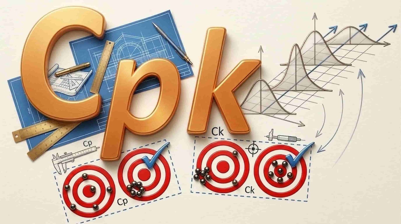
Statistical Quality Control
In high-volume manufacturing, ensuring that every part matches the CAD model is critical. Cpk helps engineers quantify the reliability of the molding process and the quality of the tooling.
- Cpk < 1.0: The process is not capable. A significant number of parts will fall outside the acceptable tolerance limits. Immediate process or tooling adjustments are required.
- Cpk = 1.0: The process is marginally capable, but any slight shift in temperature or pressure will result in defective parts.
- Cpk = 1.33: The industry standard for a capable process. This indicates a 4-sigma level of quality, which is acceptable for most consumer and industrial parts.
- Cpk = 1.67 or higher: An excellent, highly capable process (5-sigma or better). Essential for critical medical, aerospace, or automotive components.
GBM Pro Tip: Target a Cpk of 1.33 or higher for standard production runs. If your Cpk drops below 1.0, you must immediately halt the process and inspect for variations in melt temperature, injection pressure, or mold cooling.
What are the benefits of injection molding?
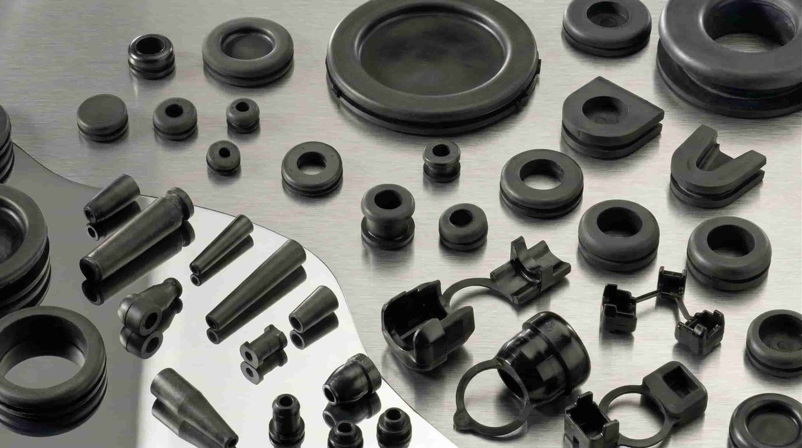
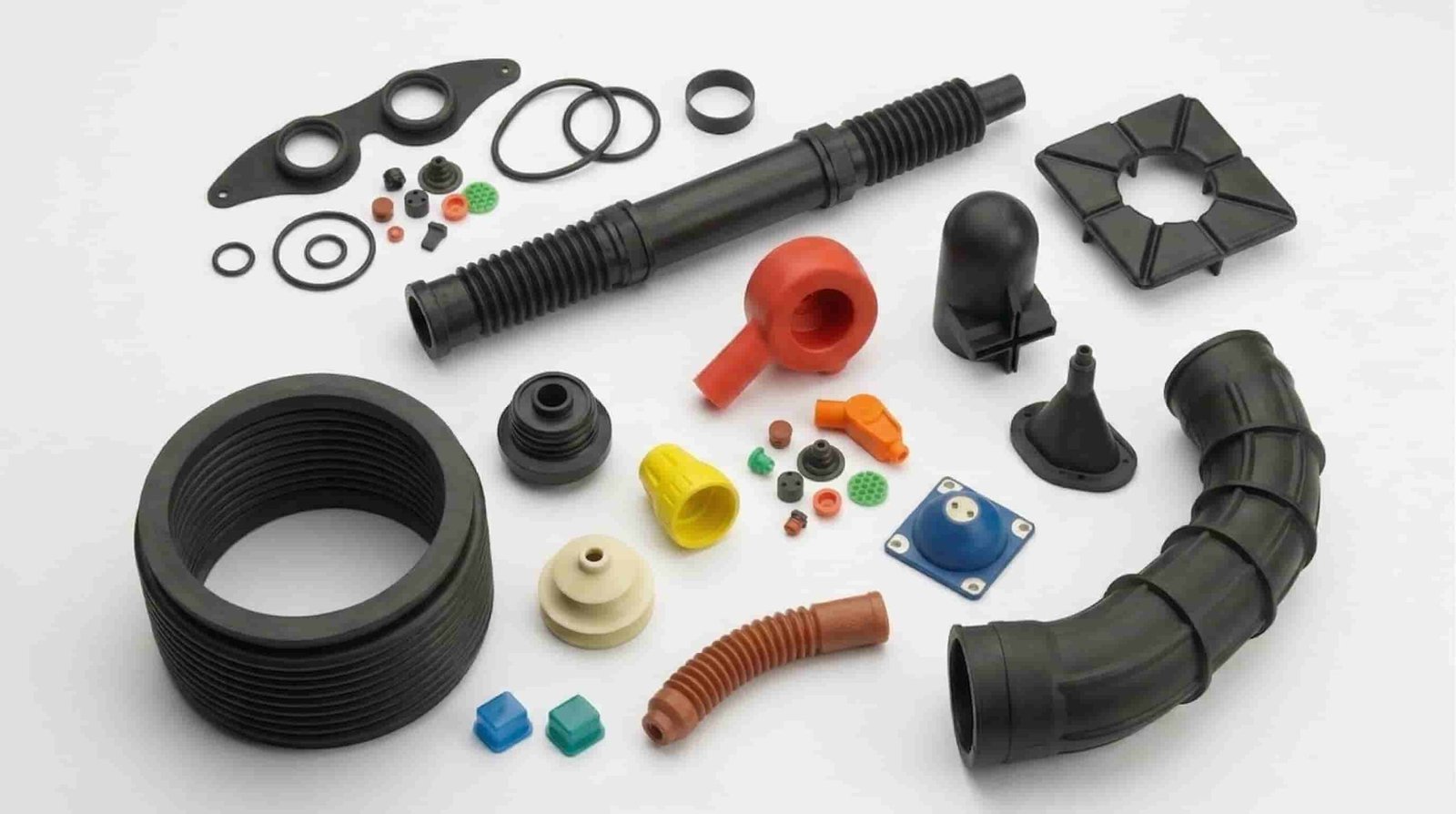
Injection molding offers unparalleled advantages for mass production, including extremely low per-part costs, rapid cycle times, high repeatability, and the ability to create complex geometries. It also supports a vast range of materials and allows for co-molding or inserting metal components.
Primary Production Advantages
When scaling a product from prototype to mass market, no other plastic manufacturing method offers the same blend of speed, cost-efficiency, and material versatility.
- High Efficiency: Once the mold is created and the press is calibrated, cycle times can be as short as 10 to 30 seconds, allowing for thousands of parts to be produced daily.
- Complex Part Design: With the use of side-actions, lifters, and complex parting lines, highly intricate parts with detailed features can be molded in a single step.
- Enhanced Strength: Unlike 3D printing, which creates parts in layers, injected parts are solid, homogenous, and structurally superior.
- Minimal Waste: Runners and sprues can often be ground up and recycled back into the process (regrind), minimizing environmental impact and material costs.
GBM Pro Tip: Maximize the benefits of this process by consolidating multiple components into a single molded part. This reduces assembly time, lowers BOM complexity, and significantly cuts overall manufacturing costs.
Key Features & Comparison
Understanding the specific constraints and features of injection molding compared to other manufacturing methods like 3D printing or CNC machining is crucial for engineers. Selecting the right process depends entirely on production volume, material requirements, and part complexity.
🎥 Top 10 DFM Rules: Explore our quick visual guide to optimizing wall thickness, draft angles, and rib structures for flawless, high-strength plastic parts.
Manufacturing Process Comparison
Engineers must weigh upfront tooling investments against long-term unit costs when choosing a manufacturing technology.
When scaling production, engineers must weigh upfront investments against unit costs. Here is how injection molding stacks up against alternative methods:
| Feature | Injection Molding | CNC Machining | 3D Printing (FDM/SLA) |
|---|---|---|---|
| Initial Setup Cost | Very High (Tooling required) | Low to Medium | Very Low |
| Unit Cost at Scale | Very Low | High | High |
| Production Speed | Extremely Fast (seconds/part) | Slow (minutes/hours) | Very Slow (hours/part) |
| Material Options | Thousands of thermoplastics | Metals and hard plastics | Limited specialized resins |
| Surface Finish | Excellent (Custom textures) | Good (Tool marks visible) | Fair (Layer lines visible) |
GBM Pro Tip: While tooling costs for injection molding are high upfront, the amortization over hundreds of thousands of parts makes it the most economical choice for high-volume production runs.
Cost & Buying Factors
The total cost of an injection molding project is driven by mold complexity, material selection, production volume, and part size. Tooling represents the largest initial capital expenditure, while cycle time and material dictate the ongoing piece price.
🎥 Smart Tooling Strategies: Learn how to design out expensive undercuts and utilize pass-through cores to drastically reduce your mold complexity and tooling costs.
Breakdown of Production Costs
Budgeting for a new molded part requires analyzing both the non-recurring engineering (NRE) costs and the continuous production expenses.
- Mold Cavitation: A single-cavity mold is cheaper to build but results in a higher piece price. A multi-cavity mold costs more upfront but drastically reduces the cost per part.
- Tooling Material: Aluminum molds are cheaper and faster to machine, ideal for low volumes. Hardened steel molds (like H13) are expensive but necessary for millions of cycles.
- Part Complexity: Features like undercuts, internal threads, and side holes require complex mechanical actions (cams, lifters) in the mold, which can double or triple the tooling cost.
- Resin Selection: Commodity plastics like PP and ABS are inexpensive, while engineering-grade resins like PEEK or Ultem will significantly increase the unit price.
GBM Pro Tip: To drastically reduce your tooling budget, eliminate undercuts wherever possible. If an undercut is unavoidable, try using pass-through cores or sliding shutoffs instead of expensive side-action cams.
Why Trust GBM for Your Plastic Injection Molding & DFM Needs?
Great part design is only theory until it meets the reality of the mold. At GBM, we bridge the gap between complex CAD models and high-volume production reality.
- Proactive DFM & Moldflow Mastery: We don’t just quote parts; we optimize them. Before cutting any steel, our engineering team conducts rigorous DFM reviews to identify draft issues, optimize wall thicknesses, and perfect gate locations. This collaborative approach saves our clients thousands of dollars in tooling rework.
- Precision Tooling for Global Standards: Achieving a consistent Cpk of 1.33 or higher requires world-class tooling. We build premium molds engineered to maintain strict dimensional stability, ensuring your components are export-ready and meet the rigorous quality standards required by North American and European markets.
- Educational Partnership: We believe in empowering engineers. Through our comprehensive design guidelines and short educational video resources, we demystify the complexities of plastics manufacturing so you can make confident, cost-effective design decisions.
- End-to-End Execution: Whether you need a rapid aluminum prototype tool or a multi-cavity hardened steel mold for millions of cycles, GBM handles the entire lifecycle under one roof to guarantee seamless scalability and uncompromising quality.
Bring your designs to life with precision. Partner with GBM’s engineering experts to ensure your next plastic component is perfectly optimized for manufacturability.
Conclusion
Mastering injection molding design is essential for producing high-quality, cost-effective plastic components. By adhering to strict DFM principles, optimizing wall thicknesses, and applying appropriate draft angles, engineers can ensure highly efficient and defect-free manufacturing.
Next Steps for Production
Successfully launching a molded product requires moving systematically from design validation to full-scale manufacturing.
- Conduct a DFM Review: Analyze the final CAD model for draft, thickness, and gating locations.
- Run Mold Flow Simulations: Verify that the mold will fill completely without air traps, weld lines, or excessive warpage.
- Prototype: Use 3D printing or CNC machining to verify form, fit, and function before committing to steel tooling.
- T1 Sampling: Order the first test shots (T1) from the initial tool to inspect for dimensional accuracy and cosmetic defects.
GBM Pro Tip: Partner with your manufacturing team early in the design phase. A collaborative DFM review before cutting steel can save thousands of dollars and weeks of rework.
Ready to move from CAD to production?
Send your 3D models to GBM today for a comprehensive, free DFM analysis.