Insert Molding Manufacturer for Custom Plastic Parts
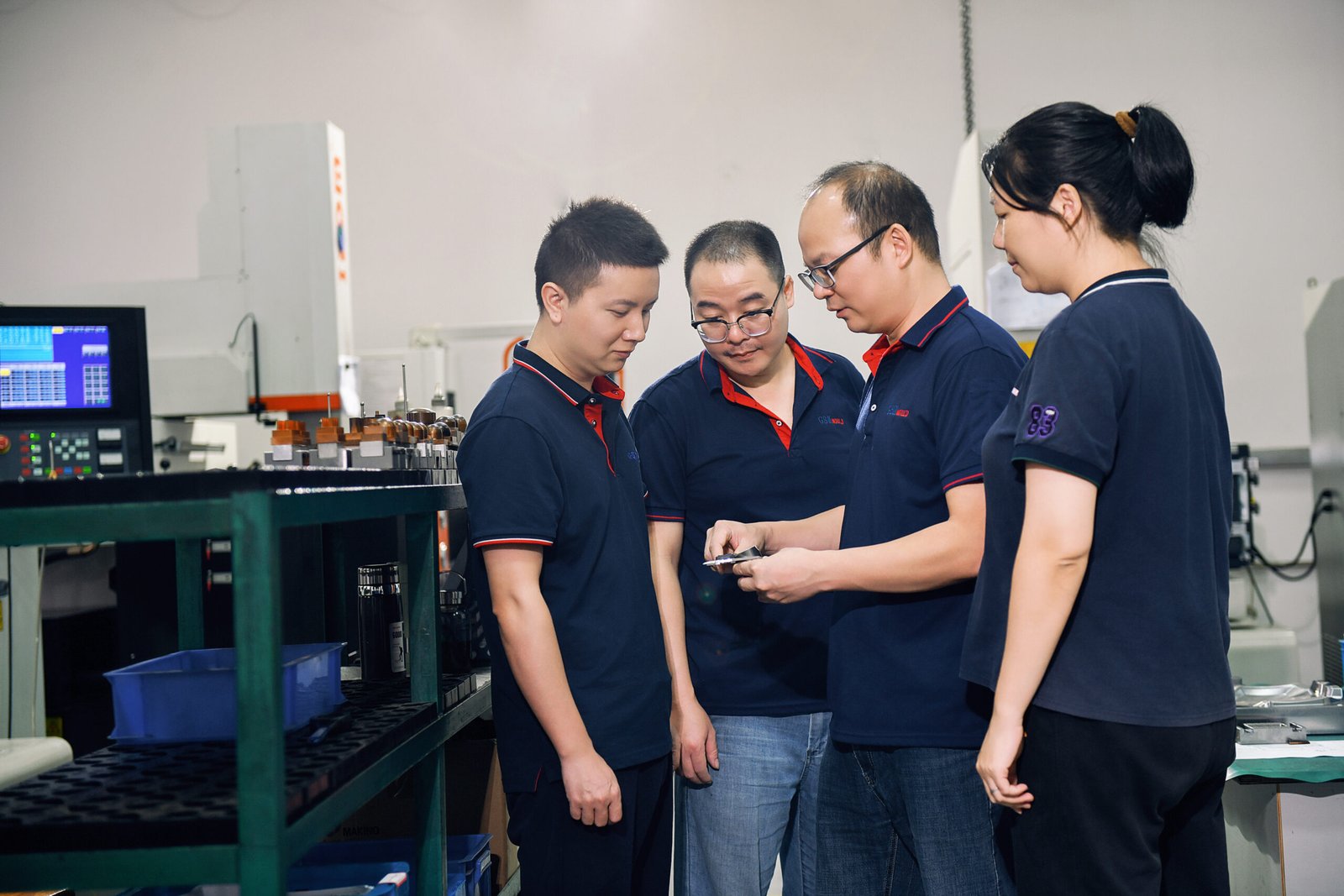
GBM provides custom insert molding services for metal inserts, brass threaded nuts, steel pins, terminals, bushings and electronic components molded into plastic parts. We support DFM review, insert positioning, mold making, T1 trial, inspection and injection molding production for prototype, small-batch and volume projects.
DFM Review Before Tooling | Insert Positioning & Thread Protection | Mold Making + Injection Molding Support | ISO 9001 Quality Control
Trusted by industry leaders








What is Insert Molding?
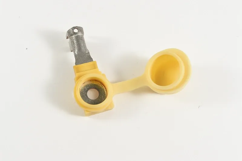
Insert molding is a plastic injection molding process where a metal insert or other pre-placed component is loaded into the mold before molten plastic is injected. After molding, the insert becomes integrated into the plastic part, helping create stronger threads, electrical contact points, shaft supports, bushings or reinforced assembly areas.
Unlike post-installed inserts, insert molding forms the insert and plastic into one molded part during the injection process. Unlike overmolding, insert molding usually focuses on metal inserts, terminals, pins, sleeves or embedded components rather than soft-touch or two-material plastic surfaces.
Primary Benefits of Insert Molding
Insert molding combines pre-placed inserts with injection molded plastic in one molding cycle. It can reduce secondary assembly, improve thread strength, add wear resistance, integrate electrical contact points and make plastic parts stronger in key load areas. However, it should be reviewed together with insert cost, loading method, mold structure and annual production volume.
Reduced Secondary Assembly
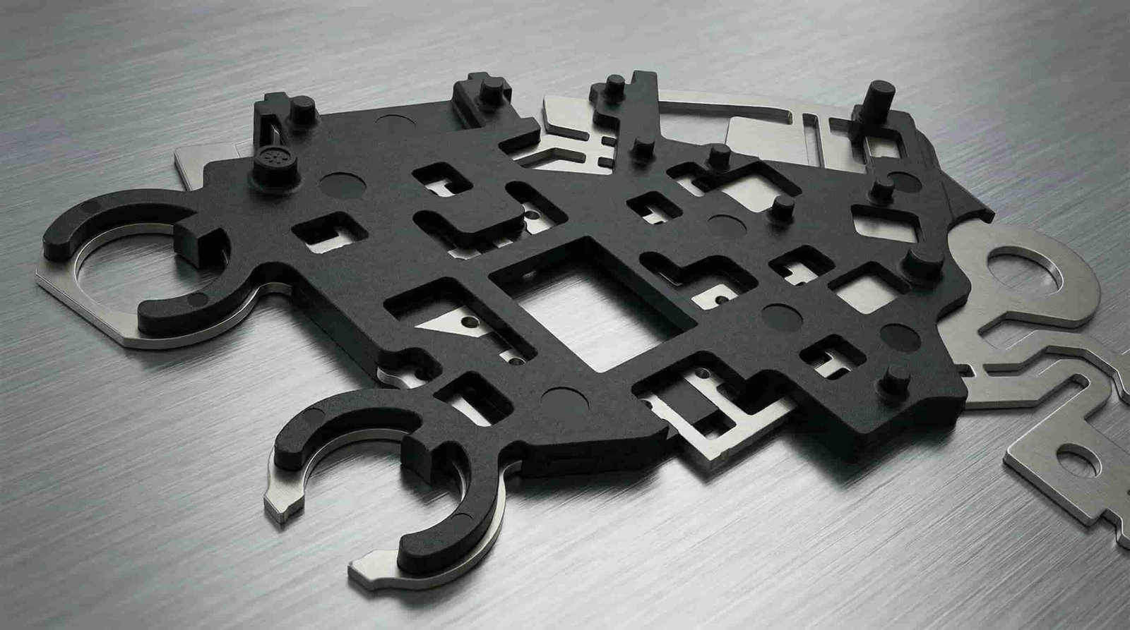
Metal inserts, threaded nuts or terminals are molded into the plastic part during injection molding, reducing separate insertion, fastening, welding or post-assembly steps.
Stronger Thread and Load Areas
Threaded inserts, bushings and sleeves can improve repeated screw assembly strength compared with plastic threads alone.
Better Insert Position Consistency
The insert position can be controlled by mold pockets, locating pins, core pins or fixtures during molding, reducing insert depth and angle variation.
Integrated Electrical or Mechanical Function
Terminals, pins and contact parts can be molded into housings or connectors to create integrated functional plastic parts.
Lower Part Weight Than All-Metal Parts
Plastic can replace unnecessary metal volume while metal inserts remain in critical load, thread, contact or wear areas.
Suitable for Medium-to-High Volume Production
Insert molding is more valuable when the production volume can justify mold structure, insert loading, fixture design and inspection requirements.
When Should You Choose Insert Molding?
Make informed decisions for your manufacturing process by understanding the optimal use cases and limitations of insert molding technology.
Ideal Scenarios
Insert molding is suitable when a plastic part needs metal threads, repeated screw assembly, terminals, pins, bushings, wear-resistant areas or embedded functional components. It is often used when post-installed inserts may create extra labor, unstable insert depth, weak pull-out strength or assembly variation.
When to Reconsider
Insert molding may not be the best option when the design is still changing, the annual volume is very low, the insert position is not critical, or a secondary insertion process can meet the strength requirement at lower cost. In these cases, heat staking, ultrasonic insertion, press-fit inserts or prototype validation may be reviewed before investing in insert molding tooling.
Common Applications
Discover the typical components and parts that benefit most from precision insert molding capabilities.
Common Inserts We Mold Into Plastic
| Insert Type | Typical Use |
|---|---|
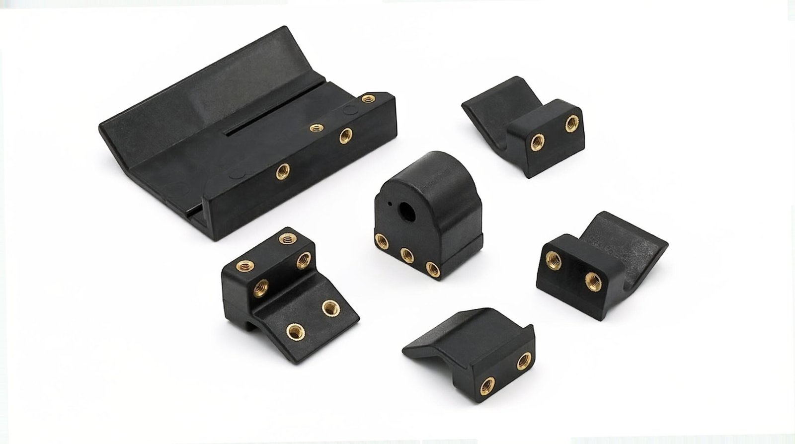
| Brass threaded inserts | Screw bosses, plastic housings, covers and repeated assembly parts |
| Steel pins and shafts | Positioning, support, hinge, shaft or wear areas |
| Stainless steel inserts | Corrosion-resistant or higher-strength applications |
| Copper terminals | Electrical contact points and connector parts |
| Metal sleeves and bushings | Shaft support, wear resistance and rotating structures |
| Stamped metal parts | Conductive plates, brackets and embedded metal frames |
| Selected electronic components | Connector housings, PCB supports and selected encapsulation projects after temperature, pressure and electrical requirements are reviewed |
Plastic and Metal Materials Used in Insert Molding
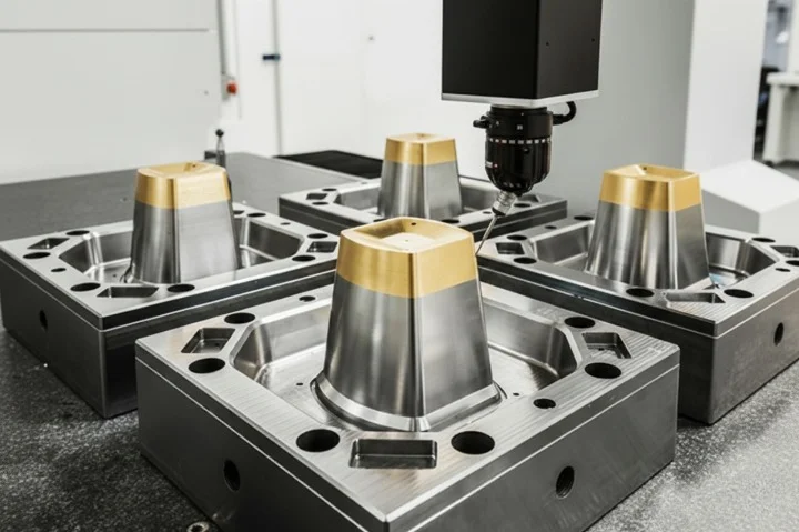
Material selection depends on part function, assembly load, temperature requirements, and plastic shrinkage behavior around the insert.
Material selection should be reviewed according to part function, insert material, processing temperature, plastic shrinkage, assembly load, electrical requirement and long-term use environment. There is no fixed plastic-and-insert combination that fits every project.
Plastic Materials
| Plastic Material | Typical Insert Molding Use | Design Notes |
|---|---|---|
| ABS | Electronic housings, covers and brackets | Good processability, but boss strength and thread load should be reviewed |
| PC | Clear covers, impact-resistant housings and precision parts | Stress cracking risk around metal inserts should be reviewed together with wall thickness, insert edge radius, screw load and molding condition |
| PA6 / PA66 Nylon | Functional housings, clips, brackets and wear-resistant parts | Moisture control and shrinkage around inserts are important |
| PBT | Automotive connectors, electrical housings and terminal parts | Terminal position and flow direction matter |
| PPS / PEEK | High-temperature connectors and high-performance engineering parts | PPS and PEEK require stricter mold temperature, insert material stability, gate design and venting review because of higher processing temperatures |
| PP | Low-density housings and simple insert parts | Shrinkage and boss deformation should be checked |
Insert Materials
| Insert Material | Typical Use |
|---|---|
| Brass | Threaded inserts, nuts and repeated screw assembly |
| Stainless steel | Corrosion-resistant or higher-strength insert applications |
| Steel | Pins, shafts, sleeves and load-bearing areas |
| Copper | Electrical terminals and conductive features |
| Aluminum | Lightweight inserts where strength and wear requirements allow |
Design Guidelines for Successful Insert Molded Parts
Insert molded parts should be designed around insert retention, plastic shrinkage, wall thickness, gate direction, insert tolerance and assembly load.
The following points are design starting references, not fixed rules. Final wall thickness, boss diameter, gate position, insert feature and inspection method should be confirmed according to resin, insert geometry, thread size, load direction and expected production volume.
1. Insert Retention Features
Use knurling, grooves, undercuts, hex shapes or other anti-rotation features when the insert needs pull-out or torque resistance.
Enough Plastic Around the Insert
Keep enough wall thickness around the insert to reduce cracking risk caused by shrinkage stress, screw load or thermal expansion difference.
Avoid Sharp Insert Edges
Sharp insert corners may create stress concentration. Radius, chamfer or surface treatment should be reviewed before tooling.
Gate Direction Should Not Push the Insert
Gate location and flow direction should be reviewed to reduce insert shift, tilt or wash-away during injection.
Thread Protection Is Critical
For threaded inserts, core pin fit, insert inner diameter tolerance and shut-off area should be checked to reduce plastic flash inside threads.
Consider Pull-Out and Torque-Out
For load-bearing parts, required pull-out force and tightening torque should be confirmed before mold design.
Review Loading Method Early
Manual loading, fixture-assisted loading or robotic loading affects mold design, cycle time, cost and part consistency.
Common Insert Molding Defects and Solutions
Insert molding has more risk points than standard injection molding because insert tolerance, insert position, mold shut-off, plastic shrinkage and gate direction all affect final part quality. GBM reviews these risks during DFM and T1 trial to reduce insert movement, thread flash, cracking, weak pull-out strength and dimensional variation.
| Defect | Common Cause | GBM Control Method |
|---|---|---|
| Insert shift or tilt | High injection pressure, weak insert holding, poor locating fit | Review gate direction, insert pocket, locating pin and T1 sample position |
| Plastic flash inside thread | Loose insert ID tolerance, poor core pin fit, worn shut-off | Check insert tolerance, core pin fit and use Go/No-Go thread gauge inspection |
| Cracking around insert | High shrinkage stress, sharp insert edge, thin boss wall | Review wall thickness, insert edge radius, material toughness and gate position |
| Poor pull-out strength | Shallow knurling, weak boss structure, poor plastic fill | Review insert geometry, undercut, gate location and packing condition |
| Poor torque resistance | Weak anti-rotation design or straight knurl only | Review diamond knurl, cross knurl, hex shape or anti-rotation features |
| Sink mark near insert | Excess plastic mass around boss | Core out thick sections and adjust holding pressure / cooling time |
| Warpage near insert | Uneven cooling, material shrinkage, unbalanced packing | Review cooling layout, material shrinkage and sample dimensions |
| Terminal or pin deformation | Insert is too thin, injection pressure is too high, support is weak | Review insert support, loading fixture, gate direction and molding pressure window |
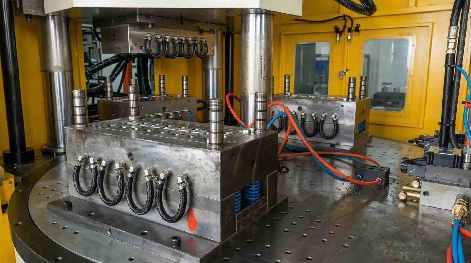
Pull-Out Strength and Torque-Out Review for Insert Molded Parts
For threaded inserts, bushings, sleeves and metal pins, appearance inspection is not enough. Pull-out strength and torque-out resistance may need to be reviewed according to screw size, insert geometry, plastic material, boss wall thickness and assembly load.
Pull-Out Strength
Pull-out strength measures the axial force required to pull the insert out of the plastic. It is affected by insert length, knurl depth, undercut design, plastic fill, boss wall thickness and molding condition.
Torque-Out Resistance
Torque-out resistance measures the rotational force required to turn the insert inside the plastic boss. It is affected by insert diameter, knurl pattern, plastic material and wall thickness around the insert.
GBM Review Method
GBM can support pull-out and torque-out sample review based on project requirements. For critical parts, the required force value, screw type, tightening torque and test method should be confirmed before mold making.
Insert Molding for Electronics Parts and Connector Housings
For electronics projects, insert molding is often used for connector housings, terminal blocks, PCB supports, threaded bosses, sensor housings and plastic parts with conductive pins. The main risks are terminal movement, plastic flash, heat damage, poor sealing, warpage and unstable contact position.
For heat-sensitive electronic components, GBM recommends reviewing the insert material, loading method, molding temperature, injection pressure and functional test requirement before tooling. Not every electronic component is suitable for direct insert molding.
| Electronics Part Risk | GBM Review Method |
|---|---|
| Terminal movement | Insert pocket, locating pin, fixture and gate direction review |
| Plastic flash around terminal | Shut-off area, insert tolerance and T1 inspection |
| Heat-sensitive component damage | Material temperature and insert loading process review |
| Warpage around terminals | Cooling layout, wall thickness and packing review |
| Connector fit issue | Cavity dimension, terminal position and sample inspection |
| Sealing requirement | Structure review and test requirement confirmation |
Insert Loading Options for Different Production Volumes
The insert loading method affects mold structure, cycle time, labor cost, part consistency and automation investment. GBM reviews the part design, insert quantity, insert size, annual volume and inspection requirements before recommending manual loading, fixture-assisted loading or semi-automated insert loading.
Manual Insert Loading
Manual insert loading is suitable for prototype trials, engineering validation and small-batch insert molded parts. Operators place metal inserts, threaded nuts, pins, terminals or bushings into the mold before each injection cycle.
This method keeps the initial tooling and fixture cost lower, but cycle time is longer and operator consistency must be controlled through clear loading steps, insert trays and visual inspection.
Fixture-Assisted Loading
Fixture-assisted loading is suitable when the project needs better insert position consistency but full automation is not yet justified. Custom trays, loading jigs, pre-positioning plates or magnetic holding tools can help operators place inserts faster and more consistently.
This method is useful for parts with multiple inserts, terminal parts, connector housings and projects where insert angle, depth or position needs better repeatability.
Robotic / Semi-Automated Loading
Robotic or semi-automated insert loading is suitable for stable high-volume production where annual demand can justify automation investment. Automation can improve loading speed, reduce operator variation and support more stable cycle time.
However, automated loading requires higher initial cost for fixtures, feeding systems, robot programming and mold structure review. GBM usually recommends this option only when the part design is stable and the production volume is high enough.
Decision Matrix
| How GBM Chooses the Loading Method | Why It Matters |
|---|---|
| Insert quantity per part | More inserts increase loading time and fixture complexity |
| Insert size and tolerance | Small or loose inserts may need better locating tools |
| Annual volume | Higher volume may justify fixtures or automation |
| Part value and scrap risk | Expensive parts need stricter loading and inspection control |
| Required insert position | Tight position requirements may need fixtures or pre-loading plates |
| Cycle time target | Automation may help when stable cycle time is important |
Insert Molding vs Post-Installed Inserts
Insert molding is not the only way to add metal threads or inserts into plastic parts. Heat staking, ultrasonic insertion, press-fit inserts and self-tapping screws may also be considered depending on volume, strength requirement and cost target.
Insert Molding vs Overmolding: Which Process Should You Choose?
Both insert molding and overmolding combine different materials, but the design focus is different. Insert molding focuses on placing an insert or component into the mold before injection, while overmolding focuses on molding one material over another substrate.
| Factor | Insert Molding | Overmolding |
|---|---|---|
| Main combination | Metal / component + plastic | Plastic substrate + plastic / TPE / TPU |
| Typical purpose | Strong threads, terminals, pins, bushings and embedded components | Soft touch, grip, sealing, color or surface function |
| Tooling requirement | Insert positioning and loading method are important | Material bonding and second-shot process are important |
| Main risk | Insert shift, thread flash, weak pull-out or cracking | Poor adhesion, warpage, delamination or cosmetic defects |
| Best for | Threaded housings, connectors, terminals, shaft supports | Handles, grips, seals, covers and two-material parts |
Not sure whether your part needs insert molding or overmolding? Send your 3D drawing, insert information and material requirement. GBM will review the process route before quotation.
How to Choose an Insert Molding Service Provider
When comparing insert molding service providers, do not only compare mold price. A good insert molding supplier should understand insert tolerance, loading method, mold shut-off, gate direction, thread protection, pull-out / torque requirement and injection molding production.
| What to Check | Why It Matters |
|---|---|
| DFM before tooling | Reduces insert shift, cracking and thread flash risk |
| Insert positioning method | Affects insert depth, angle and repeatability |
| Mold shut-off and core pin fit | Critical for threaded inserts and terminal parts |
| Loading method | Manual, fixture-assisted or robotic loading affects cost and consistency |
| Electronics project experience | Important for terminals, connector housings and PCB supports |
| Pull-out / torque review | Helps verify assembly strength for threaded inserts |
| Mold making + molding support | Reduces communication gaps between tooling and production |
| Export communication | Useful for US, Europe and overseas buyers |
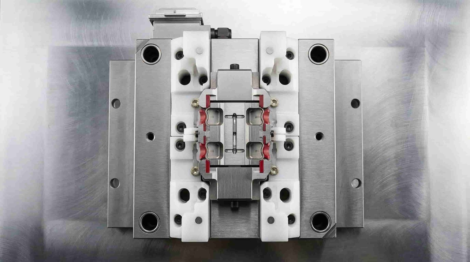
A low mold price does not always mean lower total project cost. If insert tolerance, mold shut-off, loading method or inspection plan is not reviewed before tooling, the project may face thread flash, insert shift, weak pull-out strength or high scrap rate during production.
Supporting Global Buyers
GBM is based in Shenzhen, China, and supports overseas insert molding buyers with custom mold making, T1 samples, inspection feedback and molded part production. For buyers comparing insert molding suppliers in the United States, Europe or other regions, GBM can be considered as an overseas manufacturing partner when engineering communication, tooling cost and production support are important.
Insert Molding Cost Factors
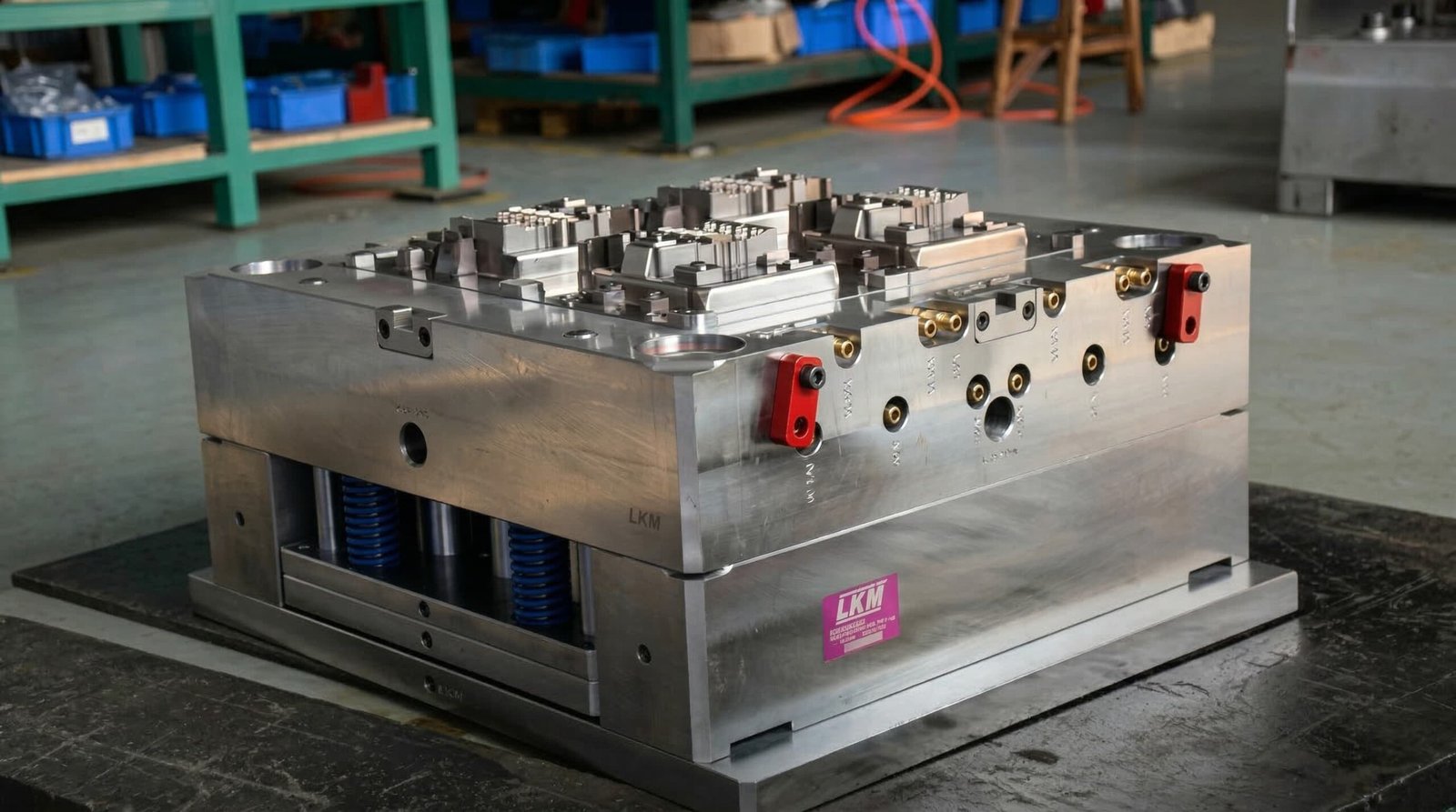
Insert molding cost is affected by both the molded plastic part and the pre-placed insert. A simple brass threaded insert project may be economical, while a multi-insert electronics housing with strict terminal position, flash control and testing requirements may need more tooling and inspection work.
For insert molded parts, the lowest mold quote is not always the lowest total cost. Insert loading time, scrap risk, fixture design, thread inspection and assembly failure risk should also be considered.
| Cost Factor | Why It Affects Cost |
|---|---|
| Insert type | Standard brass nuts are simpler; custom terminals, pins or machined inserts add cost |
| Insert tolerance | Loose insert tolerance can cause flash, tilt, thread issues or unstable positioning |
| Number of inserts per part | More inserts increase loading time, fixture complexity and inspection work |
| Plastic material | PC, PA, PPS, PEEK and glass-filled materials require different temperature and shrinkage control |
| Loading method | Manual loading lowers initial cost; automation improves unit cost at higher volume |
| Mold cavity number | More cavities increase mold cost but may reduce unit cost when annual demand is high |
| Thread / terminal protection | Core pin fit, shut-off areas and flash control increase tooling precision requirements |
| Pull-out / torque testing | Mechanical testing adds QC work but helps verify assembly performance |
| Production volume | Higher volume can justify better fixtures, automation and multi-cavity molds |
Industries That Use Insert Molding
Automotive
Sensor housings, connector parts, brackets, clips and plastic components with terminals, threaded inserts or bushings.
Electronics
Connector housings, PCB supports, terminal blocks, device housings and plastic covers with embedded metal contacts or threaded bosses.
Industrial Equipment
Handles, knobs, pump components, shaft supports, gears and wear-resistant plastic parts with metal inserts.
Power Tools
Motor housings, trigger parts, battery contact structures and reinforced plastic components.
Home Appliances
Knobs, threaded housings, washing machine parts and appliance assembly components.
Medical and Precision Plastics
Precision housings, covers and fluid-related plastic parts where insert position, clean appearance and stable tolerance are important.
Why Work With GBM
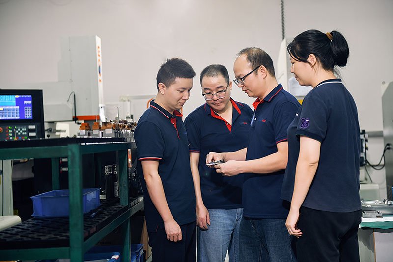
With over a decade of dedicated experience, our engineering team masters the complexities of overmolding and insert molding. We anticipate thermal expansion issues and design robust molds that ensure perfect encapsulation without damaging delicate electronic or metal inserts.
Insert Positioning Control
GBM reviews insert tolerance, mold pocket, locating pin, core pin fit and gate direction before tooling to reduce insert movement risk.
Thread Protection and Flash Review
For threaded inserts, we review insert ID tolerance, core pin fit and shut-off areas to reduce plastic flash inside threads.
Manual / Fixture / Robotic Loading Review
We recommend manual loading, fixture-assisted loading or semi-automated loading according to insert quantity, annual volume and cost target.
Preliminary DFM Feedback
Before tooling, GBM reviews part drawings, insert drawings, material, wall thickness and assembly requirements to identify early molding risks.
T1 Sample and Trial Correction
T1 samples can be reviewed for insert position, thread condition, flash, deformation, shrinkage and assembly fit before production.
Mold Making + Injection Molding Production Support
GBM supports mold design, mold making, trial feedback and injection molding production in one workflow, reducing communication gaps between tooling and molding.
Quality Control & Facilities
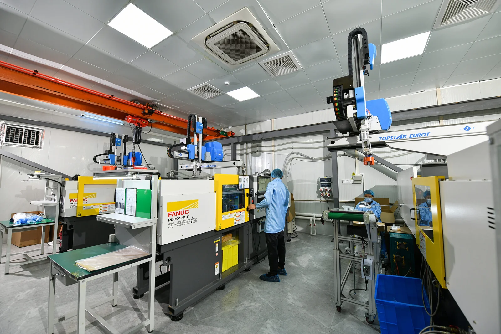
Equipped with advanced vertical and horizontal injection machines specifically calibrated for complex insert molding projects. GBM supports in-process inspection for insert presence, insert position, thread condition, visual flash and sample dimensions. Go/No-Go thread gauge inspection, pull-out review and torque-out review can be arranged according to project requirements.
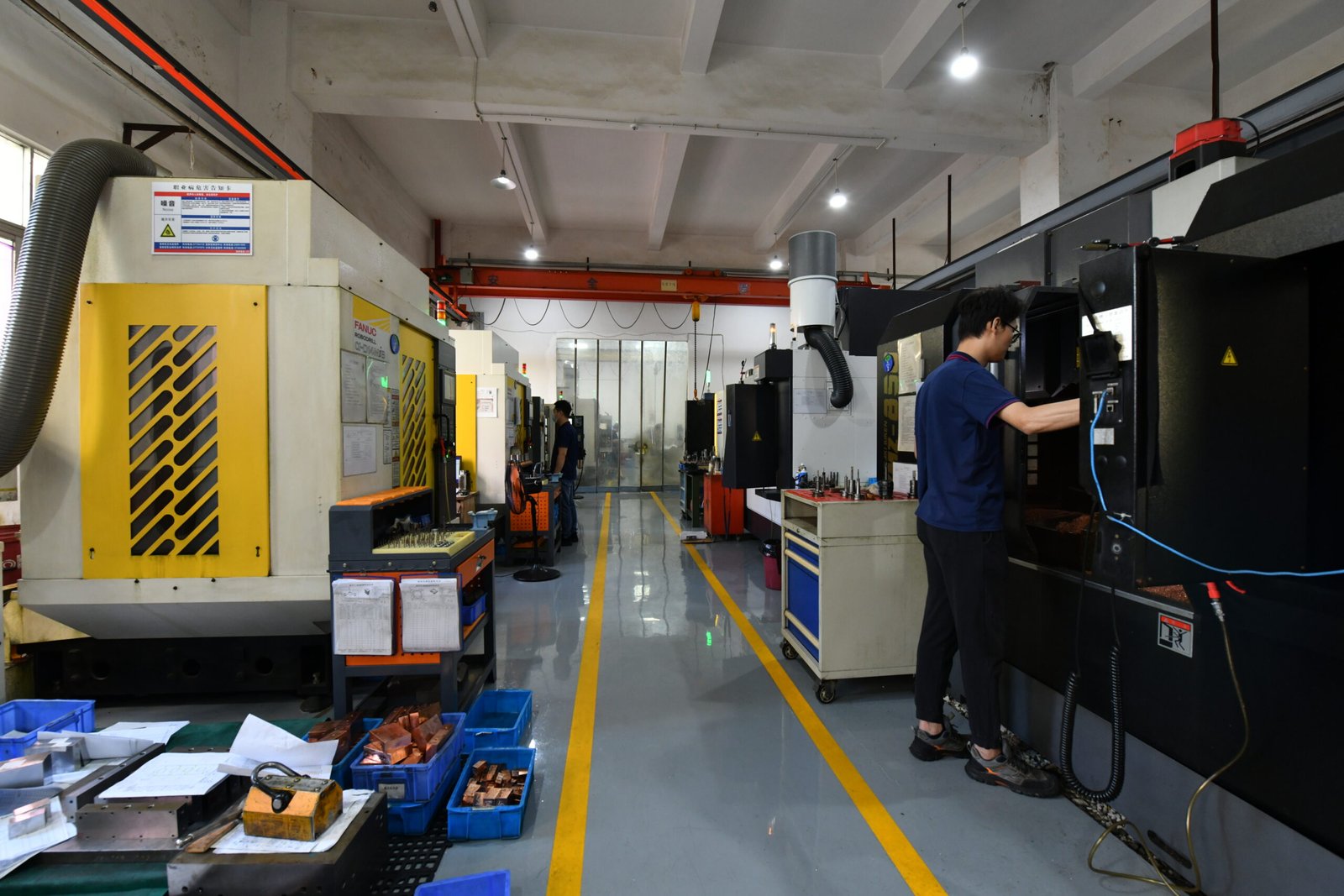
Vertical Injection Machines
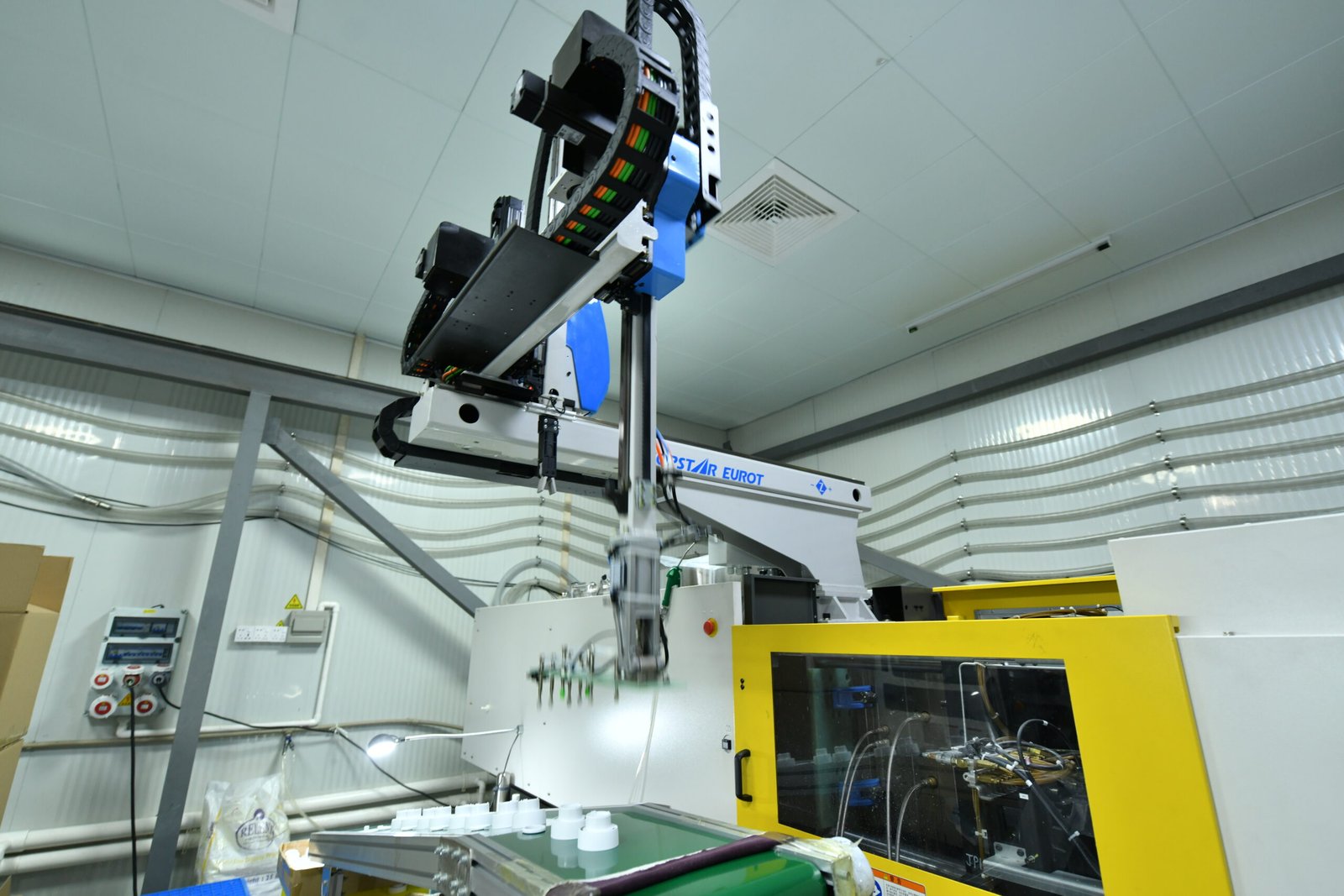
Automated Robotic Arms
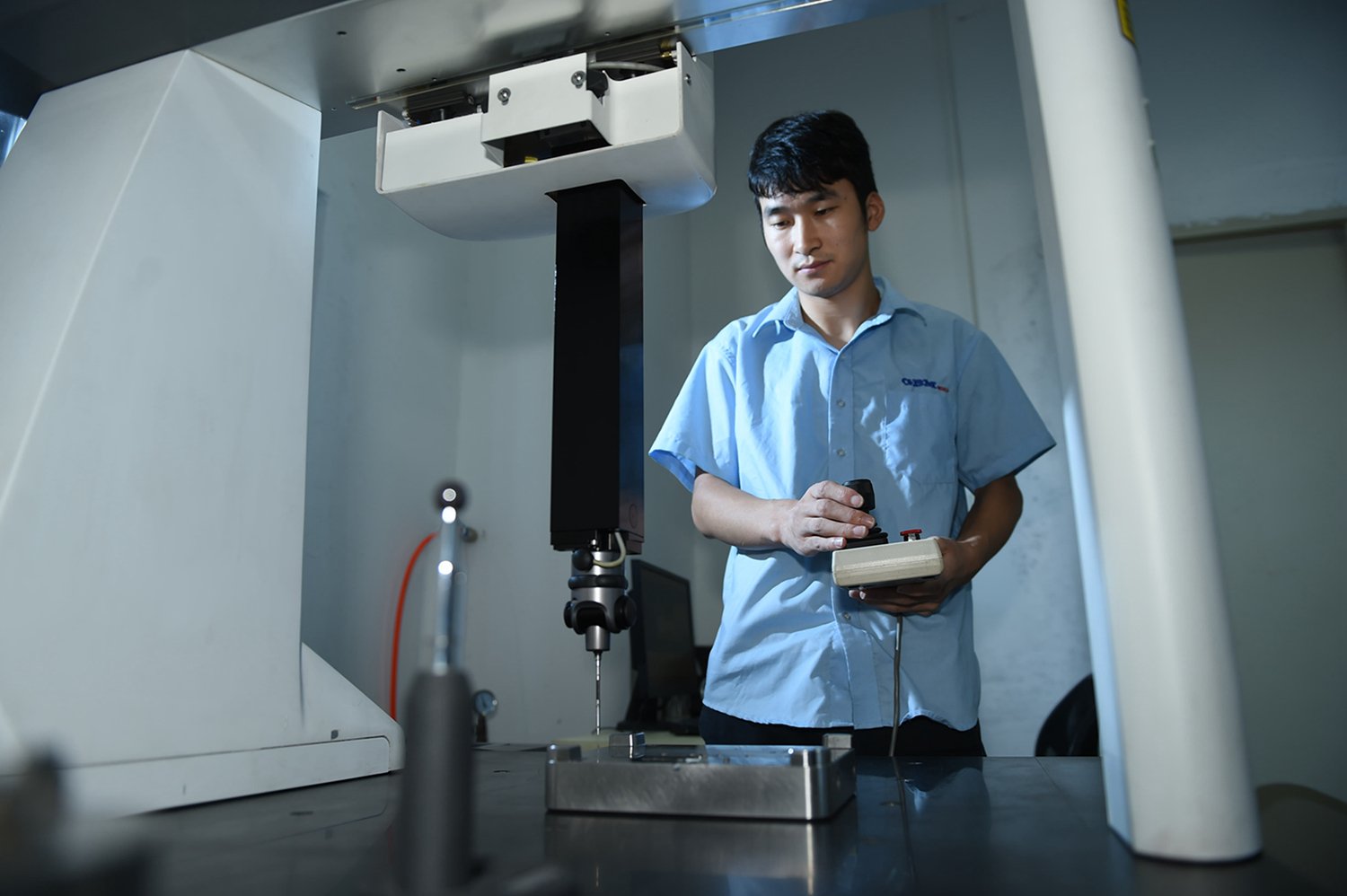
CMM Quality Inspection
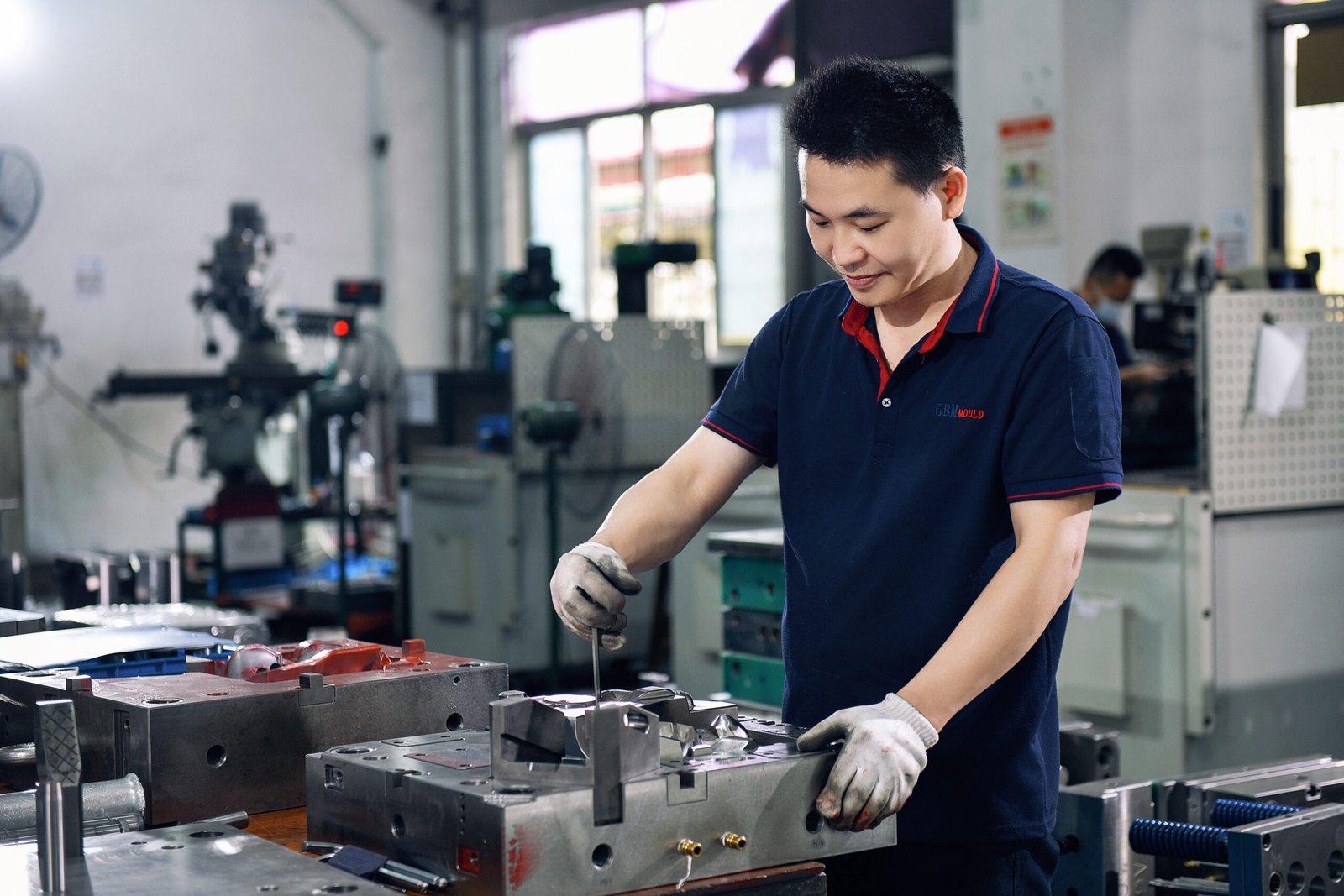
In-House Tooling Workshop
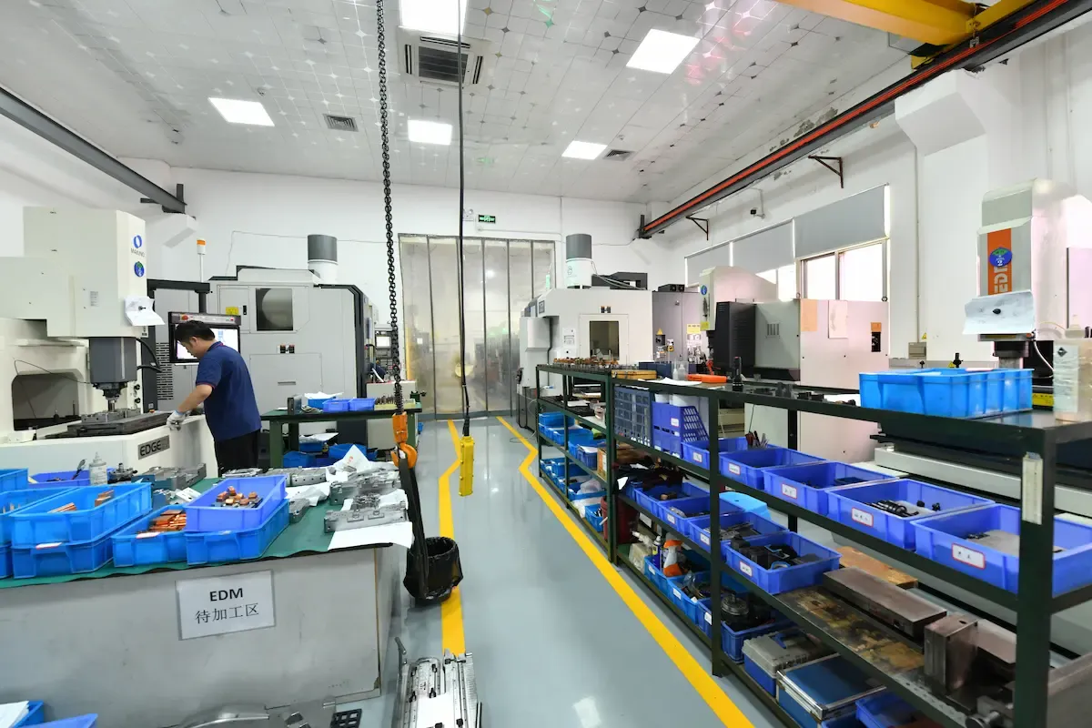
Raw Material Warehouse
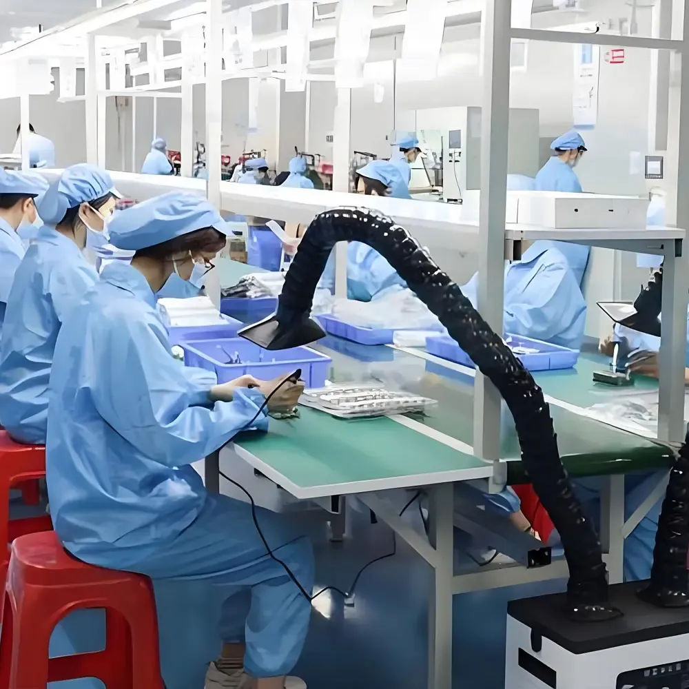
Clean Assembly & Visual Inspection
Frequently Asked Questions
What is insert molding?
Insert molding is a specialized injection molding process where molten plastic is injected into a mold cavity containing a pre-placed part (the insert) to create a single integrated piece.
What are the primary benefits of insert molding?
Insert molding can reduce secondary assembly, improve thread strength, integrate metal terminals or pins, reduce part weight compared with all-metal structures and improve insert position consistency. It is most useful when the part has repeated assembly, electrical contact, wear areas or medium-to-high production volume. However, the insert cost, loading method, mold structure and inspection requirements should be reviewed before tooling.
What materials are commonly used in insert molding?
Common plastics include ABS, PC, PA6/PA66 (Nylon), PBT, PPS, PEEK, and PP. The choice depends on temperature requirements, assembly load, and shrinkage behavior.
What metals can be used as inserts?
Brass (most common for threads), stainless steel, steel, copper (for terminals), and aluminum are frequently used.
When should I choose insert molding instead of post-installed inserts?
Choose insert molding when you need higher pull-out strength, exact positioning, or when post-installation creates extra labor, unstable depth, or assembly variations.
How does insert molding compare to overmolding?
Insert molding usually combines metal (or another component) with plastic for strength and function. Overmolding typically molds a soft plastic/TPE over a rigid plastic substrate for grip, sealing, or aesthetics.
How do you prevent inserts from moving during injection molding?
Insert movement can be reduced by reviewing insert tolerance, mold pocket fit, locating pin design, gate direction, injection pressure and loading method. For critical parts, GBM checks insert position during T1 trial and may recommend fixture-assisted loading or improved insert holding features if movement is found.
What causes cracking around metal inserts?
Cracking is often caused by plastic shrinkage stress, insufficient wall thickness around the insert, sharp insert corners, or a significant difference in thermal expansion between the metal and plastic.
How do you prevent plastic flash inside threaded inserts?
Plastic flash inside threaded inserts is usually related to insert inner diameter tolerance, core pin fit, shut-off wear or injection pressure. GBM reviews the insert drawing, core pin design and shut-off area before tooling. During T1 trial, thread condition can be checked with Go/No-Go gauges according to the inspection plan.
What is pull-out strength in insert molding?
Pull-out strength is the resistance of the molded insert to being pulled out of the plastic part axially. It is improved by adding undercuts or grooves to the insert design.
What is torque-out resistance?
Torque-out resistance is the insert's ability to resist rotating within the plastic when a screw is tightened. Knurling or hex shapes on the insert help maximize this resistance.
Can insert molding be used for electronics parts?
Yes. It is widely used for connector housings, terminal blocks, PCB supports, and sensor housings to securely embed conductive pins and terminals.
How do I choose an insert molding service provider for electronics parts?
Look for a provider with experience in terminal positioning, flash control, and sealing design reviews. They should understand how to prevent terminal movement and heat damage during molding.
What industries use insert molding?
It is widely used in automotive, electronics, industrial equipment, power tools, home appliances, and precision plastic components.
What information is needed for an insert molding quote?
Please provide the plastic part 3D/2D drawing, insert drawing with tolerances, material requirements, annual volume, and any specific pull-out or assembly requirements.
Can GBM support US or overseas insert molding buyers?
Yes. GBM is based in Shenzhen, China and supports overseas buyers with DFM review, mold making, T1 samples, inspection feedback and insert molded part production. For US, European and other overseas buyers, GBM can provide remote project communication, sample photos, inspection updates, packaging photos and export support.
Does GBM sell insert molding machines?
No. GBM does not sell insert molding machines. We provide custom insert molding services, including DFM review, mold making, and injection molding production.
Can GBM help source inserts and materials?
Yes. For selected projects, GBM can help source standard brass inserts, threaded nuts, or pins. For custom inserts, drawings and tolerance requirements must be confirmed before mold making.
What Information Should You Send for an Insert Molding Quote?
Send your part drawing and insert drawing. GBM will review insert positioning, mold structure, loading method and production cost before quotation.
Please prepare:
- Plastic part 3D file and 2D drawing
- Insert drawing with tolerance
- Insert material and surface treatment
- Thread size, thread depth or terminal dimensions
- Plastic material grade
- Annual volume and target order quantity
- Required insert position tolerance
- Pull-out force or torque-out requirement
- Assembly screw type and tightening torque
- Sealing, packaging and export requirements
Send Us Your 3D Drawings
Upload your STP/STEP files for a comprehensive engineering review.