Creating high-precision connector molds requires a deep understanding of tooling design, material selection, and injection dynamics. Whether you are prototyping a custom electrical interface with silicone or engineering a hardened steel mold for mass production, the process dictates the reliability and conductivity of the final component. This guide covers the essential steps, materials, and techniques for manufacturing effective connector molds.
Video Guide: An industrial overview of how precision molds are manufactured for electronic connectors.
What is Connector Mold?
A connector mold is a specialized tooling device designed to shape molten material—typically thermoplastics or thermosets—into specific housing geometries for electronic or mechanical connections. These molds contain precise cavities and core pins that define the socket shape, retention clips, and pinholes necessary for the connector to mate correctly with its counterpart.
Video Guide: A specific look at finishing touches and molding techniques for connectors.
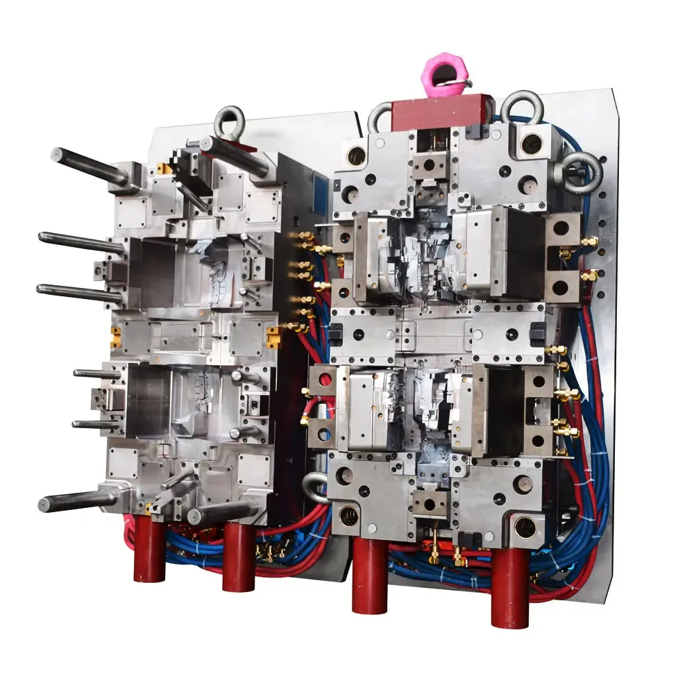
Mold Anatomy and Function
The connector mold is the negative space that creates the positive product. In the context of electronics, these molds are often “insert molds,” meaning metal pins or terminals are placed into the mold before the plastic is injected, encapsulating them to form a solid unit.
Based on our internal data and market analysis, here is the breakdown of common mold types:
| Mold Type | Primary Use Case | Durability | Cost |
|---|---|---|---|
| Prototype Mold | Testing fit and function; low volume (10-100 parts). | Low (Aluminum/Soft Steel) | Low |
| Bridge Tooling | Market entry while production tools are built. | Medium (P20 Steel) | Moderate |
| Production Mold | High-volume manufacturing (1M+ cycles). | High (Hardened Steel) | High |
GBM Pro Tip: When designing a connector mold, always account for “shrinkage.” Different plastics shrink at different rates as they cool. If your mold dimensions are exactly 1:1 with the drawing, your final connector pins may not fit. We recommend applying a shrinkage factor of 0.5% to 2% depending on the resin used.
How Does Connector Mold Work?
The molding process works by clamping the two halves of the mold together under immense pressure and injecting molten plastic into the cavity to fill the void around the core pins. Once the material cools and solidifies, the mold opens, and ejector pins push the finished connector out, ready for the next cycle.
Video Guide: A DIY demonstration of injection molding specifically for plug connector pairing bands.
The Injection Cycle
The functionality of a connector mold relies on a precise four-stage cycle. Any deviation in temperature or pressure can result in “short shots” (incomplete filling) or “flash” (excess plastic leakage).
- Clamping: The two halves of the mold (A-side and B-side) are locked together.
- Injection: Plastic pellets are melted and shot into the mold cavity through a gate.
- Cooling: Water channels inside the metal mold absorb heat, hardening the plastic.
- Ejection: The mold opens, and pins push the connector off the core.
GBM Pro Tip: Venting is critical in connector molds. Because connectors have deep, narrow blind holes for pins, air can get trapped and cause burns on the plastic. We always grind shallow vents (0.0005″ to 0.001″ deep) at the end of fill paths to let air escape without letting plastic leak.
What can you use to make your own molds?
For DIY enthusiasts or low-volume prototyping of connector molds, the most accessible materials are RTV (Room Temperature Vulcanizing) silicone rubber for flexible molds, or machined aluminum blocks for rigid injection molds. Silicone is ideal for casting resins, while aluminum is necessary if you intend to use a desktop injection molding machine.
Video Guide: Advanced techniques for making two-part silicone molds suitable for casting.
Material Selection for Tooling
Choosing the right mold material depends entirely on your production volume and the material you intend to cast or inject.
Based on our internal data and market analysis, here is the breakdown:
- RTV Silicone: Best for casting urethane or epoxy connectors. It is flexible, capturing undercuts without complex slides, but degrades after 20-50 castings.
- Epoxy Tooling Board: Good for slightly more durable molds than silicone but lacks the heat resistance for high-temp thermoplastics.
- Aluminum (7075): The standard for prototype injection molding. It machines easily and transfers heat well but creates “galling” if not lubricated.
- Steel (H13/P20): The industrial standard. Required for abrasive glass-filled plastics used in high-performance connectors.
GBM Pro Tip: If you are using silicone to mold connectors, use a “platinum-cure” silicone rather than “tin-cure.” Platinum silicones have almost zero shrinkage, ensuring that the mating surfaces of your connector remain dimensionally accurate.
Can I use Quikrete in a silicone mold?
Yes, you can cast Quikrete or similar concrete mixes into a silicone mold because silicone releases easily from cementitious materials without requiring heavy release agents. However, for “connector molds” specifically, concrete is rarely used due to its brittleness, lack of conductivity, and inability to hold the tight tolerances required for electronic pins.
Casting Concrete in Silicone
While not applicable for electronic housing, using silicone molds for concrete architectural connectors or anchors is common.
- Wall Thickness: Silicone molds for concrete need thick walls (at least 0.5 inches) or a rigid mother mold (shell) to prevent the heavy concrete from distorting the shape.
- Vibration: Concrete requires vibration to release air bubbles. Silicone absorbs some vibration, so you must vibrate the table vigorously to get a smooth surface finish.
- Cure Time: Unlike plastic which cools in seconds, concrete requires 24-48 hours to demold safely.
GBM Pro Tip: If you are experimenting with concrete connectors for artistic or structural purposes, coat your silicone mold with a light mist of vegetable oil or a specific concrete release agent. This extends the life of the silicone, which can eventually dry out from the alkalinity of the concrete.
What is the cheapest material for injection molding?
Polypropylene (PP) and High-Density Polyethylene (HDPE) are generally the cheapest thermoplastic materials available for injection molding connectors. They offer low raw material costs, low density (meaning you get more parts per pound), and process easily at lower temperatures, which reduces energy consumption and mold wear.
Video Guide: A guide on molding small parts using urethane resin, a cost-effective alternative for low volume.
Economy Material Breakdown
When cost is the primary driver for your connector housing, commodity plastics are the solution.
Based on our internal data and market analysis, here is the breakdown:
- Polypropylene (PP): Extremely chemical resistant and flexible. Ideal for “living hinges” on connector covers.
- Polyethylene (PE): Very low cost, good moisture resistance, but poor structural rigidity.
- Polystyrene (PS): Cheap and rigid, but brittle.
- ABS: Slightly more expensive than PP/PE but offers much better impact resistance and surface finish for consumer electronics.
GBM Pro Tip: Be careful with “cheap” materials for connectors carrying high current. PP and PE have lower melting points and flammability ratings compared to Nylon (PA66) or PBT. For safety-critical connectors, the cheapest material is often not compliant with UL flammability standards.
Key Features & Comparison
High-quality connector molds are defined by their precision, cooling efficiency, and ejection mechanics. Advanced molds utilize hardened steel inserts for the pin areas to prevent wear, multi-cavity layouts to increase throughput, and hot-runner systems to eliminate waste material in the runners.
Video Guide: Insights into successfully building multi-part molds for complex geometries.
Mold Classifications
The industry classifies molds based on their expected lifecycle and build quality.
Based on our internal data and market analysis, here is the breakdown:
| Feature | Class 101 (Ultra-High Volume) | Class 102 (Medium Volume) | Class 103 (Low Volume) |
|---|---|---|---|
| Cycles | > 1,000,000 | < 1,000,000 | < 500,000 |
| Base Material | Stainless Steel base | Steel base | Aluminum/Mild Steel |
| Cavity Steel | Hardened (> 50 RC) | Hardened (48-52 RC) | Pre-hardened (28-32 RC) |
| Cooling | Conformal/Complex | Standard drilled lines | minimal cooling |
| Price Factor | $$$$ | $$$ | $$ |
GBM Pro Tip: For connector molds, look for “interchangeable inserts.” Instead of machining the connector shape directly into the large mold block, we machine it into a small insert. If a pin breaks or wears out, you only replace the small insert, not the entire mold base.
Cost & Buying Factors
The cost to manufacture a custom connector mold typically ranges from $2,000 for a simple single-cavity prototype tool to over $50,000 for a multi-cavity production mold with complex side-actions. The primary cost drivers are the complexity of the connector geometry, the number of cavities, and the hardness of the steel required.
Video Guide: A detailed look at mold design execution, including keys and vents which impact cost.
Estimating Your Investment
- Part Complexity: Does the connector have undercuts or side latches? This requires “slides” or “lifters” in the mold, which significantly increases mechanical complexity and cost.
- Cavitation: A 4-cavity mold produces 4 parts per cycle but costs roughly 2.5x more than a 1-cavity mold.
- Surface Finish: High-gloss polishes (SPI A-2) require manual labor, whereas EDM (spark erosion) finishes are cheaper and standard for industrial connectors.
GBM Pro Tip: To save money on your first mold, ask for a “Master Unit Die” (MUD) insert. In this system, you only pay for the custom insert that forms your part, while the mold base (the heavy frame that holds it) is a standard reusable component owned by the molder. This can reduce tooling costs by 40-60%.
Conclusion
Making connector molds is a balance between precision engineering and material science. Whether you are utilizing 3D-printed masters for silicone casting or commissioning Class 101 steel tooling for injection molding, the success of the project relies on accurate compensation for shrinkage, proper venting, and selecting the right mold material for your volume requirements. For professional results, always validate your design with a prototype mold before committing to expensive production tooling.