Precision connector molds are the fundamental tooling required to mass-produce high-performance electronic interconnects used in automotive, medical, and consumer electronics industries. These molds determine the geometric accuracy, surface finish, and mechanical integrity of the final connector, requiring exacting tolerances often measured in microns. At GBM, we understand that mastering the molding process is essential for ensuring reliable signal transmission and structural durability in every component.
Video Guide: An overview of how precision molds are manufactured specifically for connector applications.
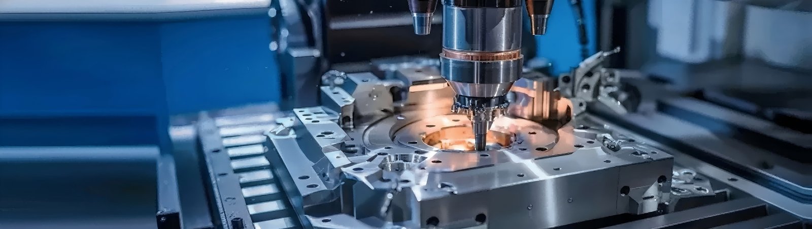
What is Connector Mold?
A connector mold is a specialized injection molding tool designed to form plastic housings and structural components for electrical connectors. It typically consists of high-grade steel plates, precision-machined cavities, and cores that shape the molten thermoplastic into complex geometries capable of holding metal contacts securely. These molds are engineered for high-volume production, extreme repeatability, and tight tolerance adherence.
Video Guide: Understanding the role of connectors within the injection molding ecosystem.
Definition and Tooling Composition
The connector mold is the heart of the manufacturing process, transforming raw plastic pellets into functional components. Unlike standard molds, connector molds must accommodate intricate details such as thin walls, fine pitch intervals between pins, and locking mechanisms. The construction usually involves hardened tool steels to withstand the abrasive nature of glass-filled engineering plastics often used in connectors.
- Cavity Plate: Forms the external shape of the connector housing.
- Core Plate: Shapes the internal features and holds the pins or inserts.
- Slider/Lifter Mechanisms: Essential for creating undercuts or side holes typical in connector latches.
- Ejection System: Precision pins that push the finished part out without damaging delicate features.
GBM Pro Tip: For high-frequency connectors, the surface finish of the mold cavity is critical. We recommend a mirror polish or specific texture to minimize signal interference and ensure smooth mating cycles.
How Does Connector Mold Work?
The process operates on the principles of thermoplastic injection molding, where plastic resin is melted and injected under high pressure into the mold cavity. The cycle involves clamping the mold shut, injecting the material, cooling it to a solid state, and finally ejecting the finished connector housing. This cycle repeats rapidly, often producing multiple parts per cycle in multi-cavity molds.
Video Guide: A detailed look at the design and process flow for plastic connectors.
The Injection Molding Cycle
The efficiency of a connector mold relies on the seamless synchronization of temperature, pressure, and time. The process is highly automated to ensure consistency across millions of parts.
- Clamping: The two halves of the mold (core and cavity) are pressed together with tonnage sufficient to resist injection pressure.
- Injection: Molten plastic (e.g., LCP, PBT, or Nylon) is shot into the mold through a runner system.
- Holding/Packing: Pressure is maintained to pack more material into the cavity as the plastic shrinks during cooling.
- Cooling: Water channels within the mold remove heat, solidifying the part.
- Ejection: The mold opens, and ejector pins push the connector out.
GBM Pro Tip: In connector molding, “venting” is non-negotiable. Improper venting leads to diesel effect (burning) at the end of fill, especially in thin-walled connector grids. We prioritize active venting channels in our mold designs.
What are the characteristics of connectors?
Connectors produced via precision molding are characterized by their electrical insulation properties, mechanical strength, and dimensional stability. Key characteristics include the “pitch” (distance between contact centers), retention force (how well they hold terminals), and resistance to environmental factors like heat and vibration. These attributes are directly dictated by the quality of the mold used.
Video Guide: Exploring the structural application and performance characteristics of connectors.
Performance Attributes
The physical characteristics of a connector are the direct result of the mold’s precision and the material selected. A high-quality mold ensures that the connector meets stringent industry standards.
- Dimensional Accuracy: Critical for ensuring the connector mates correctly with the PCB or matching plug.
- Dielectric Strength: The plastic housing must effectively insulate adjacent contacts to prevent short circuits. See Dielectric Strength for more details.
- Thermal Resistance: Connectors must withstand reflow soldering temperatures without warping.
- Mechanical Durability: The housing must endure repeated mating and unmating cycles (mating cycles).
GBM Pro Tip: When evaluating connector characteristics, pay attention to the “flash” line. Excessive flash indicates a worn mold or poor clamping, which can interfere with the connector’s assembly and sealing properties.
What are some basic characteristics of mold?
Basic characteristics of a high-quality connector mold include high hardness (usually HRC 50-52), precision venting systems, and optimized cooling channels. These molds feature multi-cavity layouts to maximize output and interchangeable inserts to allow for easy maintenance or design variations. The steel selection is paramount to resist wear from abrasive glass-filled materials.
Video Guide: Viewing a complex mold setup for connector injection molding.
Tooling Specifications
The mold itself must possess specific physical traits to guarantee longevity and part quality. The complexity of the mold directly correlates to the complexity of the connector.
Based on our internal data and market analysis, here is the breakdown of standard mold characteristics:
| Characteristic | Standard Mold | High-Precision Connector Mold |
|---|---|---|
| Steel Hardness | HRC 30-40 (P20) | HRC 50-54 (H13, S136) |
| Tolerance | +/- 0.05 mm | +/- 0.005 mm |
| Cooling System | Standard lines | Conformal cooling for rapid cycle |
| Life Cycle | 100k – 300k shots | 1 Million+ shots |
| Maintenance | Periodic | Frequent micro-cleaning required |
GBM Pro Tip: Always specify “corrosion-resistant steel” (like S136) if you are molding connectors with flame-retardant additives, as these release corrosive gases that can pit the mold surface over time.
What are molded connectors?
Molded connectors, often referred to as overmolded connectors, are cable assemblies where the connector and the cable are fused together using a molding process. This technique encapsulates the termination point, providing superior strain relief, waterproofing (IP rating), and a robust mechanical bond that prevents the cable from pulling out of the connector body.
Video Guide: A visual explanation of molded cable connectors and their benefits.
Overmolding vs. Assembly
Molded connectors differ significantly from standard assembled connectors (which snap together). The molding process creates a unified structure.
- Preparation: Wires are stripped, crimped to terminals, and inserted into a pre-mold or housing.
- Placement: The cable assembly is placed into a vertical injection mold.
- Overmolding: Plastic (often PVC or TPE) is injected over the junction, sealing the connection.
- Result: A watertight, ruggedized interface resistant to bending and vibration.
GBM Pro Tip: For outdoor applications, choose TPE (Thermoplastic Elastomer) for the overmold material. It provides better UV resistance and flexibility compared to standard PVC, ensuring the molded connector doesn’t crack in cold weather.
Key Features & Comparison
When selecting a manufacturing approach for connectors, it is vital to distinguish between standard injection molding (housing only) and insert molding (metal + plastic).
Based on our internal data and market analysis, here is the breakdown:
| Feature | Standard Injection Molding | Insert Molding |
|---|---|---|
| Process | Plastic housing molded first; contacts inserted later. | Plastic is molded around the metal contacts. |
| Cost | Lower tooling cost; higher assembly labor. | Higher tooling cost; lower assembly labor. |
| Reliability | Good; depends on assembly friction. | Superior; plastic bonds mechanically to metal. |
| Waterproofing | Requires potting or gaskets. | Inherently better sealing properties. |
| Application | General purpose headers, sockets. | Heavy-duty, automotive, waterproof connectors. |
GBM Pro Tip: Insert molding is the gold standard for high-vibration environments (like automotive engines) because the contacts cannot back out—they are permanently locked into the plastic matrix.
Cost & Buying Factors
The cost of a connector mold is driven by cavitation (number of parts per cycle), part complexity, and steel grade. A single-cavity prototype mold may cost a few thousand dollars, while a high-production, multi-cavity mold with hardened steel and hot runner systems can range from $20,000 to over $100,000. Buyers must balance upfront tooling costs with long-term piece price savings.
Pricing Drivers
Understanding where the money goes helps in negotiation and project planning.
- Cavitation: More cavities = higher mold cost but lower unit price.
- Complexity: Undercuts, side-actions, and unscrewing mechanisms increase engineering hours and machining costs.
- Steel Grade: High-grade stainless steel (for medical/food use) costs significantly more than standard tool steel.
- Runner System: Hot runner systems reduce waste (sprues) but increase the initial mold investment.
GBM Pro Tip: Do not cut corners on the mold base. A cheap mold base can flex under pressure, causing flash and dimensional instability. Investing in a rigid, high-quality mold base pays for itself by reducing rejection rates.
Conclusion
The “Connector Mold” is the pivotal technology behind the reliability of modern electronics. Whether dealing with standard housing injection or complex overmolded cable assemblies, the process requires a synergy of precision engineering, high-quality materials, and expert process control. From the hardness of the steel to the intricacies of the cooling channels, every characteristic of the mold impacts the final product’s performance.
At GBM, we specialize in delivering high-precision mold solutions that ensure your connectors meet the rigorous demands of the market. By understanding the process and characteristics outlined above, you can make informed decisions that optimize both quality and cost for your manufacturing projects.