Gas Assist Injection Molding Manufacturer & Design Guide
Custom gas assist injection molding for thick-wall handles, large covers, ribbed housings and cosmetic plastic parts. GBM reviews gas channel layout, gas pin position, gate direction, venting, cooling and T1 trial risks before mold cutting.
What Is Gas Assist Injection Molding?
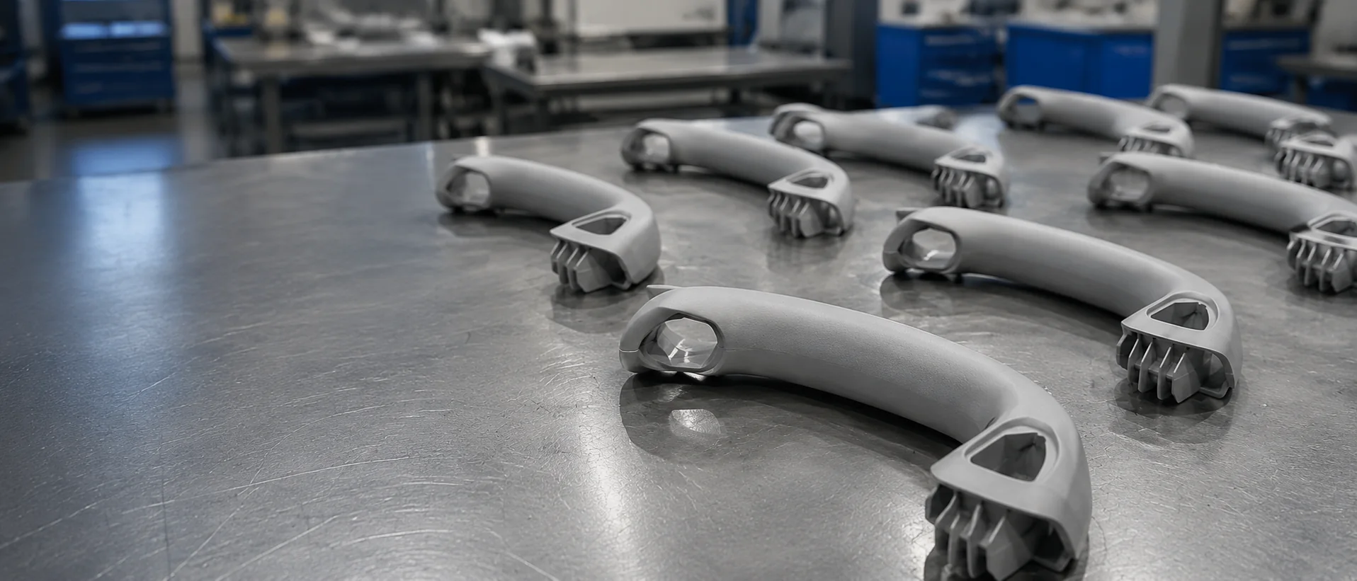
Gas assist injection molding is a plastic molding process that injects pressurized gas, usually nitrogen, after partial resin filling. The gas pushes the molten plastic through selected thick sections, forms controlled hollow channels, and helps pack the part from inside during cooling.
For thick-wall handles, tubular sections, ribbed frames and large cosmetic covers, this process can help reduce sink marks, lower part weight, improve dimensional stability and reduce excessive packing pressure when the gas path is correctly designed. Nitrogen-based gas assist is widely described as a process used after resin injection to increase internal pressure, support flow in large parts, reduce warpage and sink marks, and form hollow structures for weight reduction.
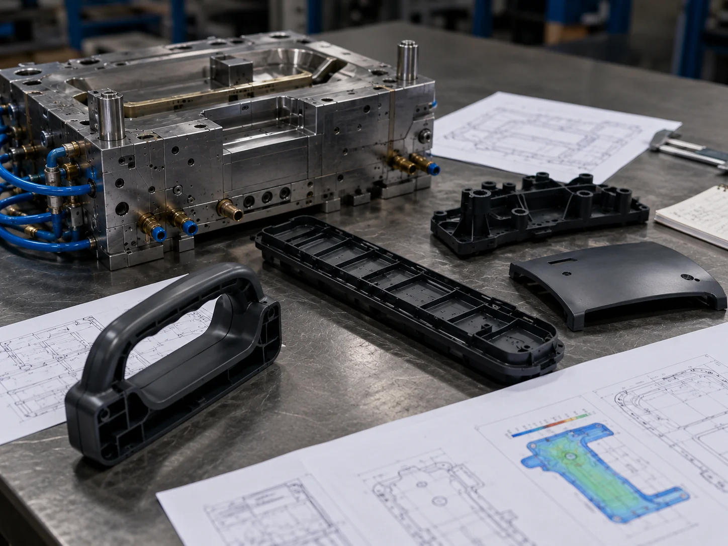
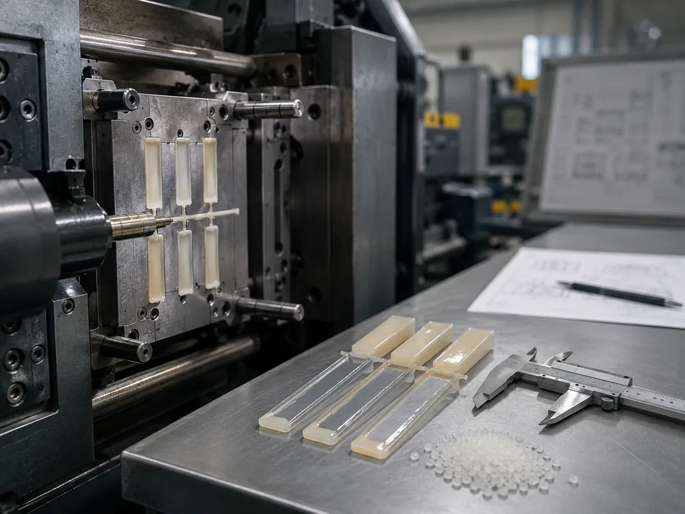
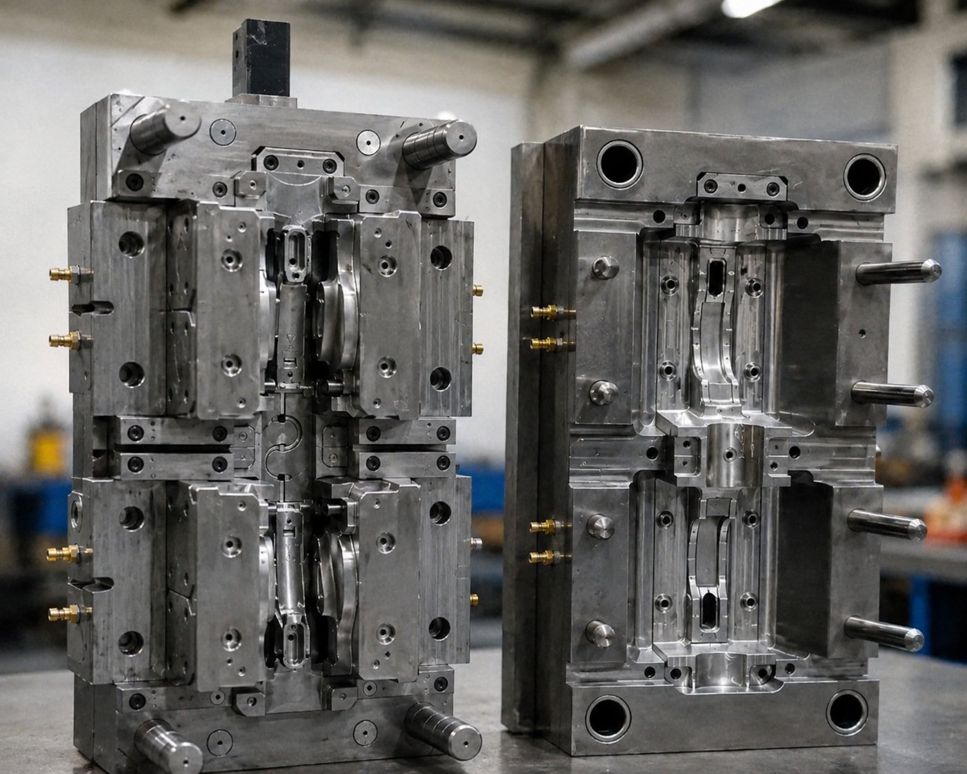
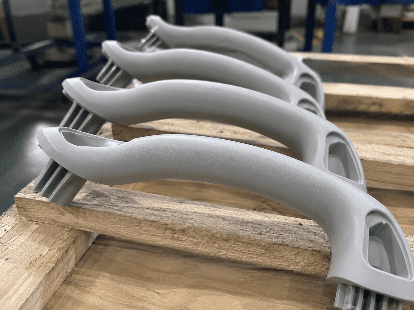
Factory Inspection: Mold, Hollow Section Sample & Caliper Check
Resin short-shot filling
Nitrogen gas injection
Gas channel formation
Gas packing and cooling
T1 sample section check
How Does Gas Assist Injection Molding Work?
In gas assist molding, nitrogen does not randomly enter the part. The gas path must be planned before mold cutting. GBM reviews the relationship between gate position, gas channel layout, wall thickness transition, gas delay time and cooling balance so that the gas can support the intended thick section instead of entering thin-wall cosmetic areas.
Resin short-shot or full-shot filling
Check gate location and melt flow direction
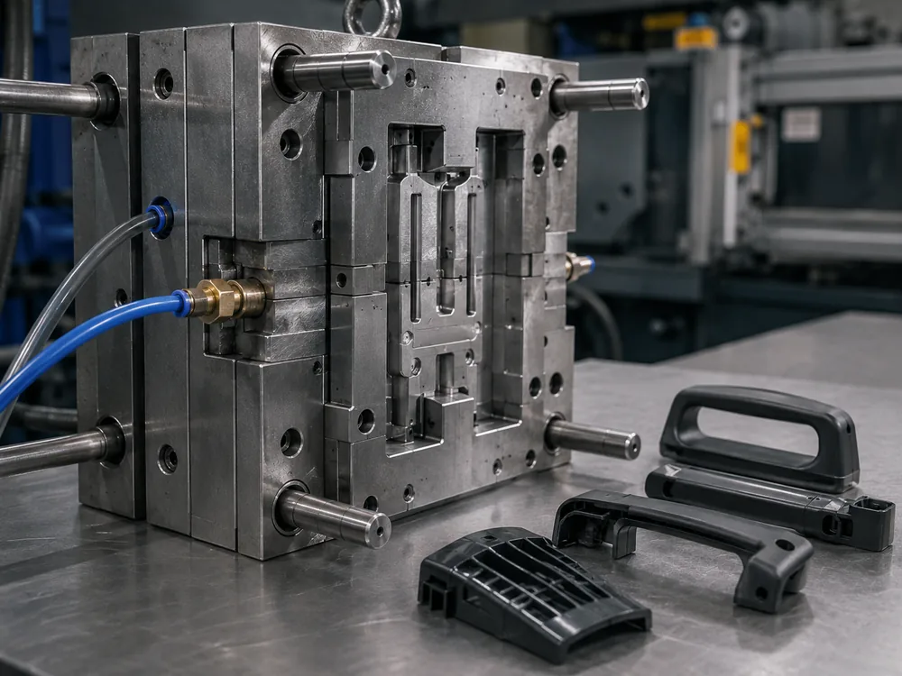
Nitrogen gas injection
Confirm gas pin / nozzle position
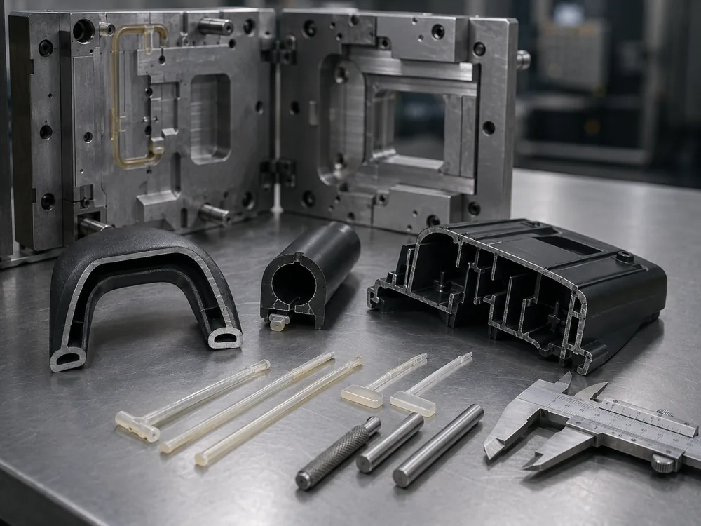
Gas penetration
Check whether gas follows the intended thick section
Gas packing and cooling
Review pressure ramp, delay time and cooling layout
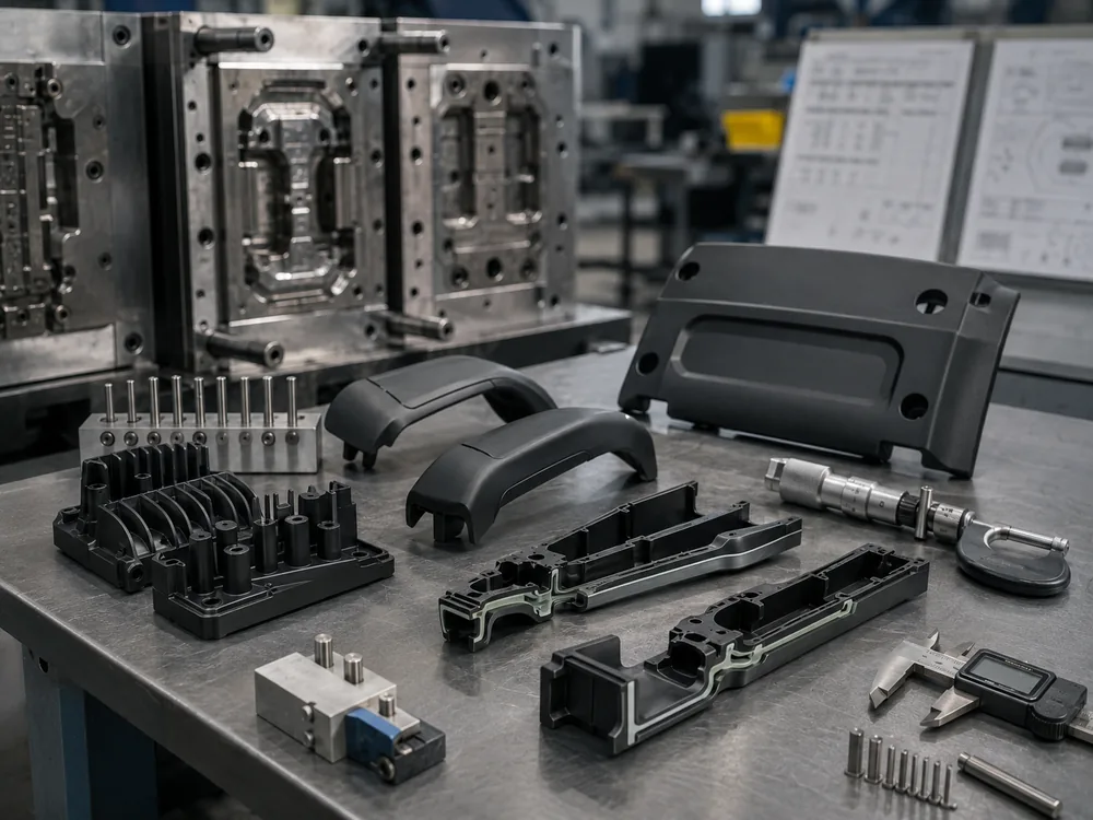
T1 sample validation
Check weight, section cut, surface marks and dimensions
Gas Assist Injection Molding
Design Guide Before Tooling
Gas assist injection molding design must be reviewed before mold cutting. Prioritizing the gas channel layout is critical, as the gas path directly impacts weight reduction, structural strength, warpage, and sink mark control. For thick-wall handles, long ribs, boss-heavy areas, and large covers, GBM Mold meticulously verifies wall transitions, gate locations, and cooling to ensure stable molding.
This guide explains the key design points buyers and engineers should confirm before starting a gas assist mold project.
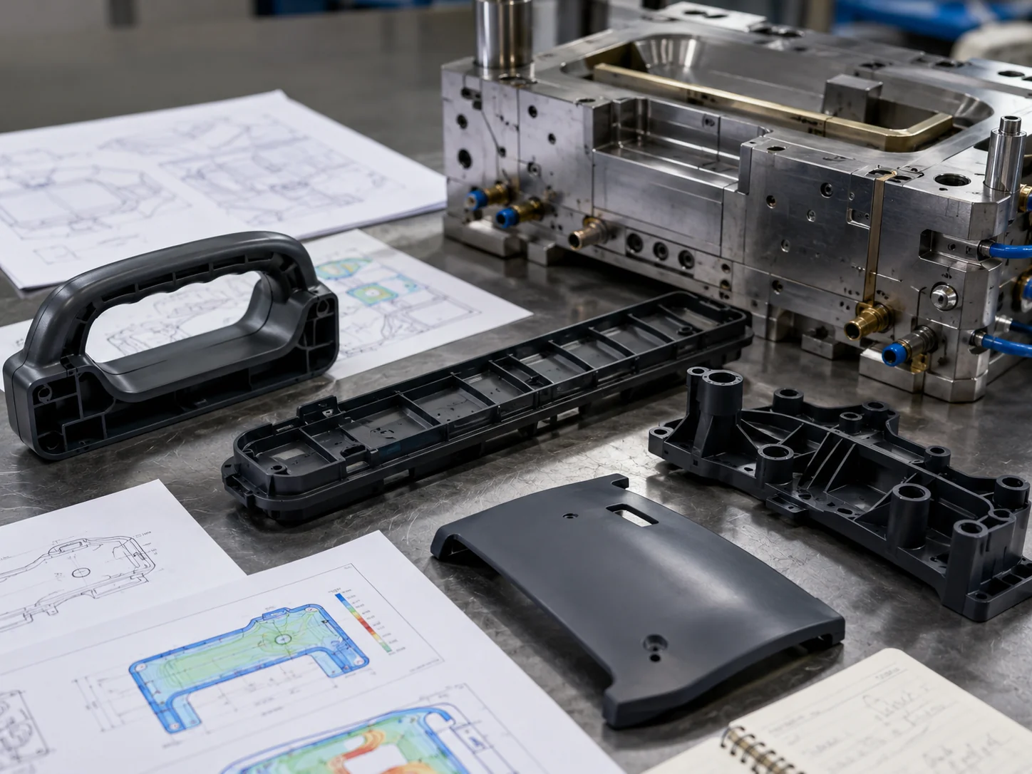
Key Design Confirmation Points
| Design Point | GBM Review Focus | Risk If Ignored |
|---|---|---|
| Wall Thickness Transition | Check thick-to-thin areas, rib roots, boss bases and handle sections | Sink marks, warpage, unstable gas penetration |
| Gas Channel Layout | Define the gas path before mold cutting | Gas may enter thin-wall areas or leave thick areas solid |
| Gas Pin / Nozzle Position | Match gas entry with resin flow and channel direction | Blow-through, short fill, incomplete gas penetration |
| Gate Location | Match melt flow direction with gas penetration direction | Unbalanced flow, surface defects, unstable packing |
| Venting | Review gas release and trapped gas risk | Burn marks, gas traps, incomplete gas movement |
| Cooling Layout | Balance cooling near hollow and solid sections | Warpage, dimensional drift, longer T1 correction |
| T1 Validation | Check delay time, pressure ramp, sample weight and section result | Mold approval risk before production |
Gas Assist Injection Molding Parameters We Review Before Tooling
| Parameter | GBM Mold Review Focus |
|---|---|
| Process Type | Internal gas assist molding, external gas assist molding, gas-assisted injection mold manufacturing |
| Typical Part Features | Thick walls, ribs, bosses, handles, tubular sections, large covers, structural frames |
| Mold Type | Custom injection mold, gas assist mold, multi-cavity mold depending on part size and production volume |
| Material Options | ABS, PP, PC, PC/ABS, PA, POM and project-specific engineering plastics evaluated for flow rate |
| Gas Medium | Usually nitrogen, based on equipment pressure settings and process cooling requirements |
| Key Tooling Areas | Gas channel layout, gas pin or nozzle position, gate and runner design, venting and cooling layout |
| Trial Validation | T1 samples, mold trial video, dimensional inspection, surface review and gas penetration check |
| Reports Available | Sample QC report, CMM report, FAI report and CPK study on request for batch stability |
| Delivery Support | Mold drawing, spare parts list, maintenance notes, packing photos and export mold preparation |
Or consult our engineers directly: Annie@gbminjection.com | +86 13632611848
Internal vs External Gas Assist Injection Molding
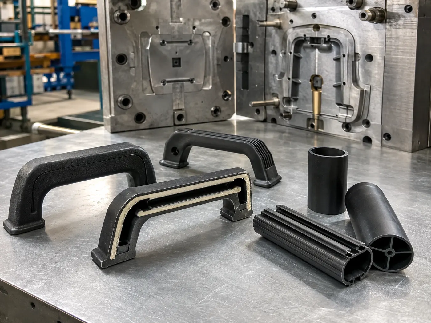
Internal Gas Assist Injection Molding
Best for handles, tubular parts, thick-wall ribs, frames and parts where hollow internal sections can reduce weight and sink marks.
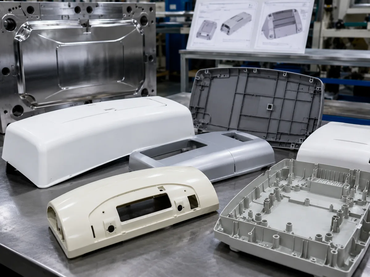
External Gas Assist Injection Molding
Best for large cosmetic covers, panels, housings and visible A-side surfaces where the backside can accept gas packing marks.
| Buyer Situation | Better Option | Why |
|---|---|---|
| Thick handle needs weight reduction | Internal gas assist | Gas can form hollow channel inside thick section |
| Large panel has A-side sink marks | External gas assist | Gas pressure can support cosmetic surface from B-side |
| Tubular or long ribbed structure | Internal gas assist | Gas follows controlled long thick section |
| Flat cover with hidden backside ribs | External gas assist | Helps reduce rib read-through on visible surface |
| Thin small part with no thick section | Conventional molding | Gas path may be unstable or unnecessary |
Industry Insight: As noted by industry experts like Mack Molding, external gas assist can beautifully improve cosmetic surfaces, but the side where gas is applied may show a wavy or sinky appearance. Therefore, external gas assist is most effective when the gas-packed side is hidden in the final assembly.
What Are the Advantages of Gas Assist Injection Molding?
Gas assist injection molding is most valuable when the part has thick sections, ribs, bosses, long handles or cosmetic surfaces that are difficult to pack with conventional injection molding. The advantage is not only “lighter weight”; the real value comes from controlling sink marks, packing pressure, warpage, cycle time and visible surface quality through gas path design and T1 validation.
| Advantage | Why It Matters for Buyers | GBM Review Point |
|---|---|---|
| Reduced Sink Marks | Useful for ribs, bosses, handles and cosmetic surfaces | Gas path close to thick section |
| Lower Part Weight | Hollow sections can reduce unnecessary resin | Section strength and durability check |
| Better Dimensional Stability | More balanced internal packing can reduce warpage | CMM / FAI sample inspection |
| Lower Packing Pressure | Helpful for large covers and long-flow parts | Gate, gas pressure and flow direction |
| Better A-Side Appearance | Useful when B-side ribs cause cosmetic sink | External gas assist feasibility |
| Integrated Structure Design | May reduce secondary assembly for handles or frames | Strength and assembly review |
Need immediate engineering support? Call us at +86 13632611848
When Should You Consider Gas Assist Injection Molding?
Gas assist injection molding is worth reviewing when a plastic part has thick sections, visible sink risk, long ribs, large cosmetic surfaces or high packing pressure problems in conventional injection molding.
| Part Condition | Gas Assist Suitability | GBM Suggestion |
|---|---|---|
| Thick handles or tubular sections | High | Review internal gas channel and section strength |
| Large cosmetic covers with B-side ribs | High | Review external gas assist feasibility |
| Long ribs or boss-heavy parts | Medium to High | Check gas path, gate and venting |
| Large part with high packing pressure | Medium to High | Compare gas assist vs conventional molding |
| Thin-wall small part | Low | Conventional injection molding may be better |
| Fully solid structure required | Low | Avoid hollow gas channel unless redesign is accepted |
| Uncontrolled branching geometry | Risky | Simulation and T1 section check required |
Design Note: Xometry categorizes gas assist parts into contained-channel and open-channel types. Parts like handles, tubes, and frames (contained-channel) are easier to control because the gas path is clearly defined by geometry. Conversely, access covers, panels, shelves, and chassis (open-channel) are more challenging because gas may escape into thin-wall areas, creating a defect known as "fingering."
Need immediate assistance? Call our experts at +86 13632611848
Gas Assist Molding Simulation & DFM Review Before Mold Cutting
For gas assist molding projects, simulation and DFM review should focus on gas penetration path, melt front position, gas channel size, gas pin location, short-shot ratio, venting and cooling balance.
CAE analysis can help predict whether the gas will follow the intended channel, but final confirmation still depends on T1 samples, section cuts, part weight comparison, surface review and dimensional inspection.
Asahi Kasei’s CAE material also explains that gas-assisted molding simulation is useful for understanding gas injection behavior and reflecting it in product design.
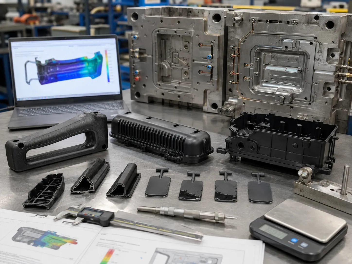
| Simulation / DFM Item | What It Helps Check | GBM T1 Confirmation |
|---|---|---|
| Gas penetration path | Whether gas follows the planned channel | Section cut / sample weight |
| Melt front position | Whether gas enters too early or too late | Short-shot sample review |
| Gas channel size | Whether the channel is too large or too small | Sink / blow-through check |
| Gas pin position | Whether gas entry is stable | T1 pressure and delay adjustment |
| Cooling balance | Hollow vs solid shrinkage difference | CMM / FAI inspection |
| Surface risk | A-side sink, gas mark, whitening | Cosmetic sample approval |
Secure & Confidential. Response within 24 hours.
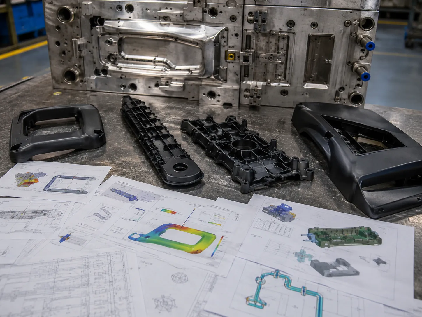
Gas Assist Mold
Design Rules Before Tooling
Define the gas path early: Before gas assist mold tooling starts, the gas path should be defined together with the part structure, gate location and melt flow direction.
Optimize channel location: The gas channel should stay close to thick sections such as handles, long ribs, tubular features and boss-heavy areas, while uncontrolled branching should be avoided to prevent one area from filling first and another area remaining solid or under-packed.
Avoid oversizing: The gas channel should not be oversized, because an excessive channel may create a flow-leader effect and leave nearby thin-wall areas unfilled.
Review structural details: Rib thickness, boss design, venting position and gas release direction must also be reviewed before mold cutting. Ribs located on gas channels may need different design rules from traditional rib structures, and venting should be planned according to the final gas movement direction. Validate during T1: During T1 trial, samples should be checked for surface marks, gas penetration, short fill, blow-through, part weight change and dimensional variation before the mold is approved for production.
Engineering & Simulation References
Gas channel size, gas entrance position, venting layout, cooling design and material behavior should be reviewed together during the early DFM stage. CAE simulation can help predict gas penetration, flow balance, shrinkage risk and possible surface defects before mold cutting. Final rules still need to be confirmed through T1 samples, part weight checking, dimensional inspection and cosmetic review.
Is Your Part Suitable for Gas Assist Injection Molding?
| Part Type | Suitability | GBM Review Direction |
|---|---|---|
| Thick handles | Highly suitable | Gas channel, hollow section, strength and surface marks |
| Tubular structures | Highly suitable | Gas penetration length, gate position and wall consistency |
| Large cosmetic covers | Suitable after review | External gas assist, A-side surface, B-side rib layout |
| Ribbed frames | Suitable after review | Rib thickness, gas path and warpage |
| Boss-heavy housings | Suitable after review | Sink marks, boss base thickness and cooling layout |
| Very thin-wall parts | Usually not first choice | Conventional molding may be better |
| Very small parts | Usually not first choice | Gas control may be difficult |
| Fully solid strength parts | Usually not first choice | Hollow gas path may not match function |
| Parts with uncontrolled gas branching | High risk | Need redesign or simulation review |
How GBM Reviews and Builds a Gas Assist Mold Project
1
Drawing and Requirement Review
GBM checks 3D drawings, 2D tolerance, material, annual quantity, cosmetic surface and assembly function.
2
Gas Assist Feasibility Review
We evaluate wall thickness, gas channel possibility, rib and boss risk, gate position and whether conventional molding may be a better option.
3
DFM and Mold Layout
The mold layout includes cavity layout, gate and runner, gas pin or nozzle position, venting, cooling and ejection review.
4
Mold Manufacturing
Mold base, cavity/core inserts, gas-related components, cooling system and surface finish are manufactured based on the approved design.
5
T1 Trial and Process Adjustment
T1 trial checks filling, gas delay time, pressure ramp, surface marks, part weight, gas penetration and dimensional result.
6
Inspection and Export Preparation
GBM provides samples, trial video, inspection report, mold photos, spare parts list, packing photos and maintenance notes.
Have a thick-wall or large cosmetic plastic part?
Send your drawing for a gas assist feasibility review covering wall thickness and gas path analysis.
Gas Assist Equipment Interface GBM Reviews During Mold Design
GBM Mold focuses on gas assist mold design, mold manufacturing, and injection molding project support, not gas assist equipment sales. During mold design, we meticulously review the gas pin or gas nozzle interface, nitrogen gas entry position, controller sequence, gas pressure adjustment range, mold cooling layout, and T1 trial setup. This ensures the mold works seamlessly with the buyer’s selected gas assist system. By optimizing how internal gas pressure forms hollow channels using nitrogen, we help our clients effectively reduce warpage, sink marks, part weight, and required clamp tonnage.
| Equipment-Related Item | GBM Review Focus |
|---|---|
| Nitrogen gas entry | Gas pin / nozzle position and access |
| Gas controller sequence | Delay time, pressure ramp and release timing |
| Pressure range | Whether the mold design can support stable gas penetration |
| Cooling system | Cooling near thick sections and hollow channels |
| T1 setup | Short-shot ratio, gas pressure and sample validation |
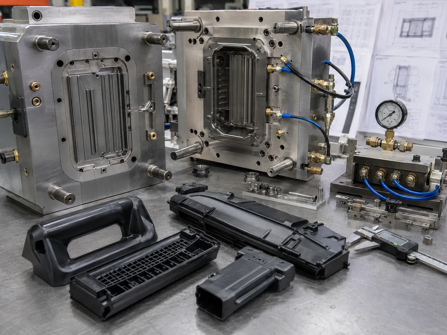
Gas Assist Injection Molding Support for US & European Buyers
GBM Mold supports overseas gas assist injection molding projects from DFM review to mold manufacturing, T1 samples, inspection reports and export mold preparation. For US and European OEM buyers, we can review 3D drawings, discuss gas channel feasibility, provide T1 photos and videos, share sample inspection reports, and prepare mold packing documents before shipment.
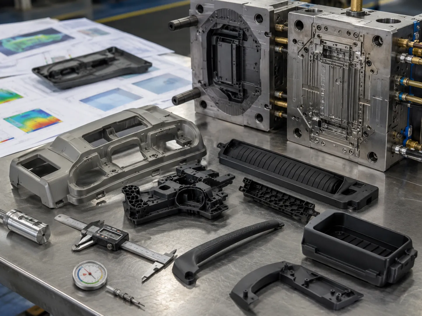
DFM Review Before Mold Cutting
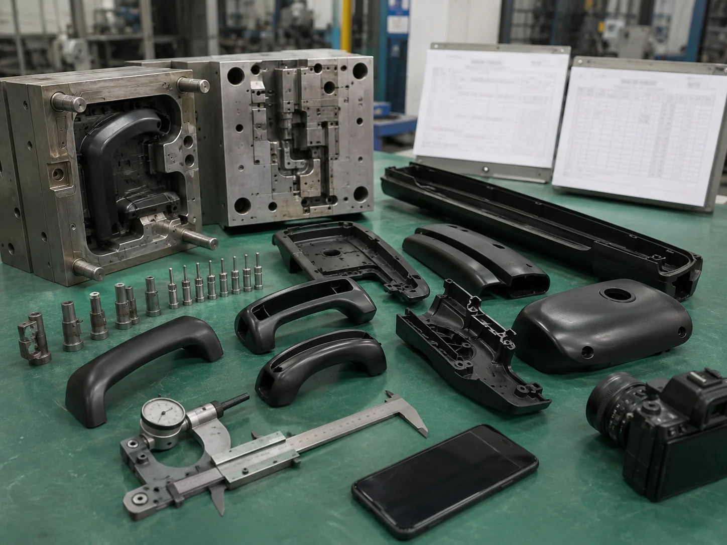
T1 Samples, Photos & Trial Video
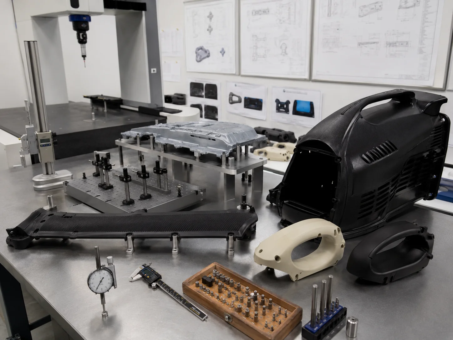
CMM / FAI Report on Request
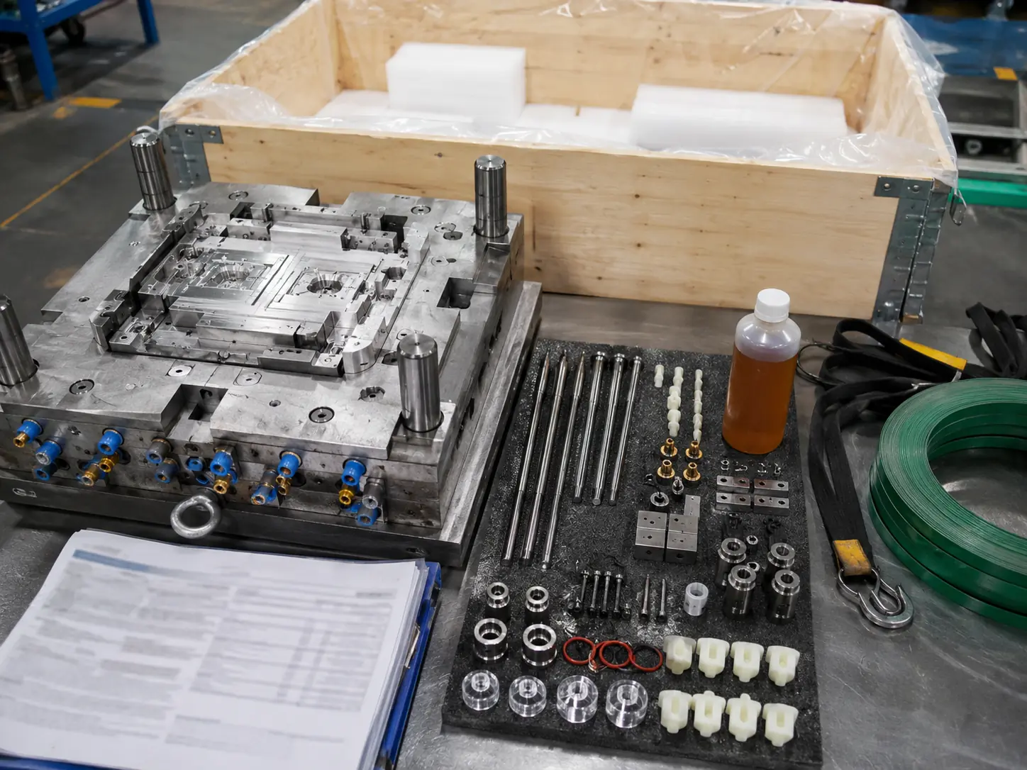
Export Mold Packing & Spare Parts List
Common Applications for Gas Assist Injection Molding
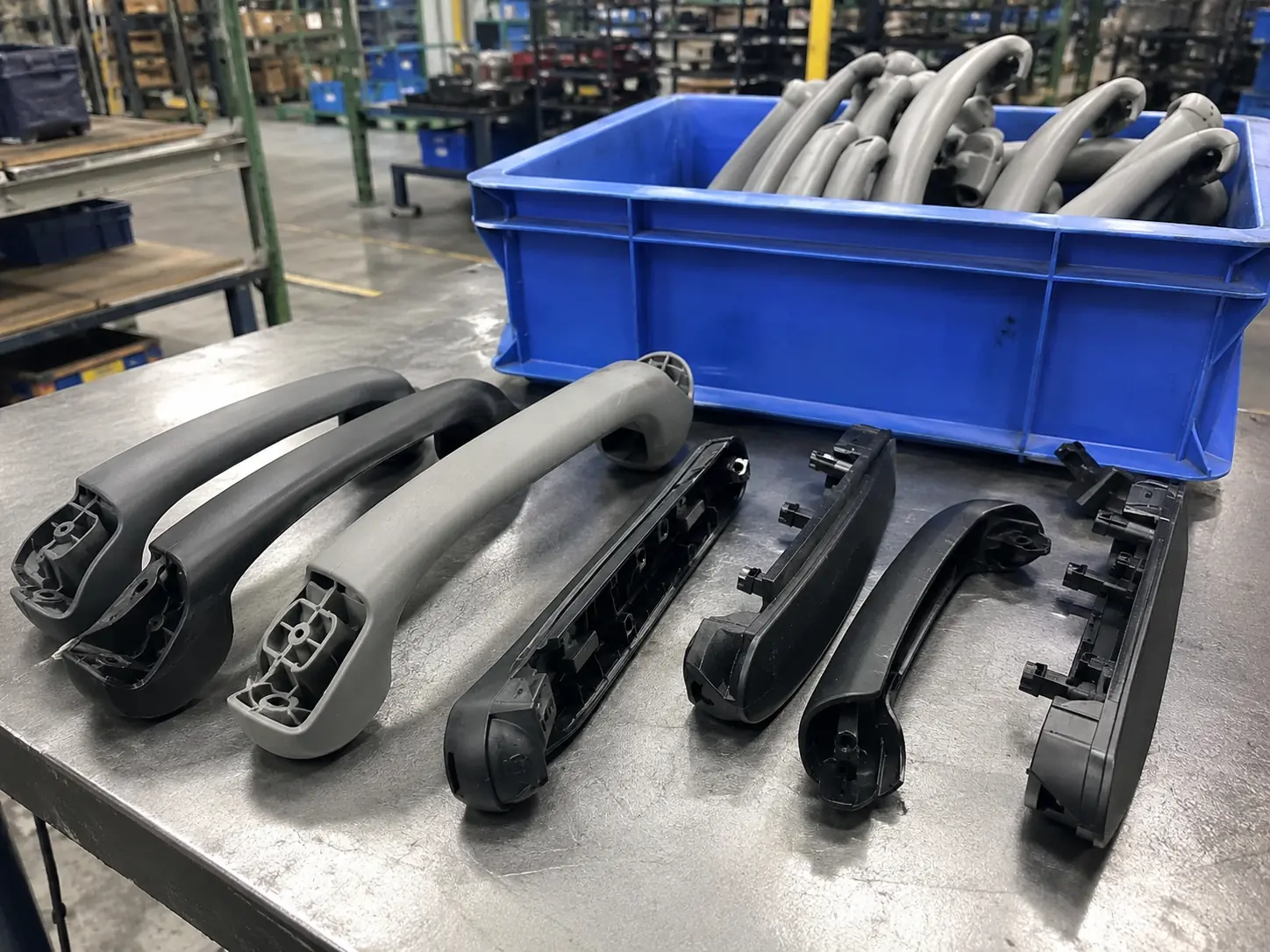
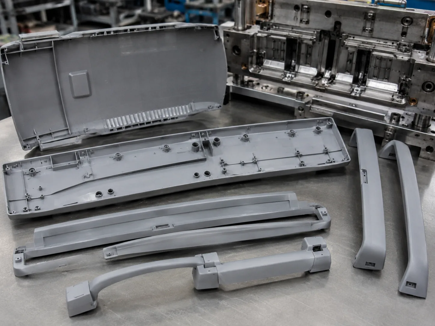
Automotive Handles & Interior Frames
Typical Part Features: thick handle base, long rib, structural frame
Buyer Concern: weight, sink mark, assembly fit
GBM Review Point: gas path, gate location, section strength, CMM inspection
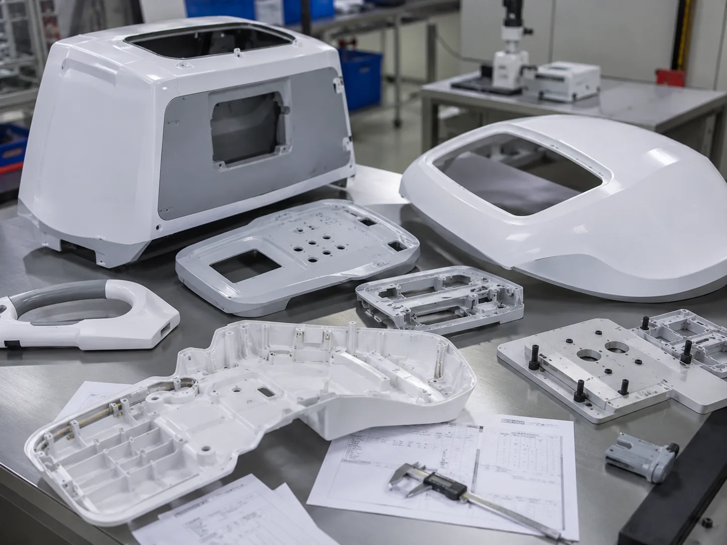
Appliance Handles & Large Covers
Typical Part Features: large cosmetic cover, hidden B-side ribs, thick grip area
Buyer Concern: A-side appearance, warpage, stable assembly
GBM Review Point: external gas feasibility, rib read-through, cooling balance
Medical Equipment Housings
Typical Part Features: large flat surface, internal bosses, structural rigidity
Buyer Concern: clean appearance, assembly accuracy, inspection documents
GBM Review Point: shrinkage control, uniform wall thickness, gas channel layout
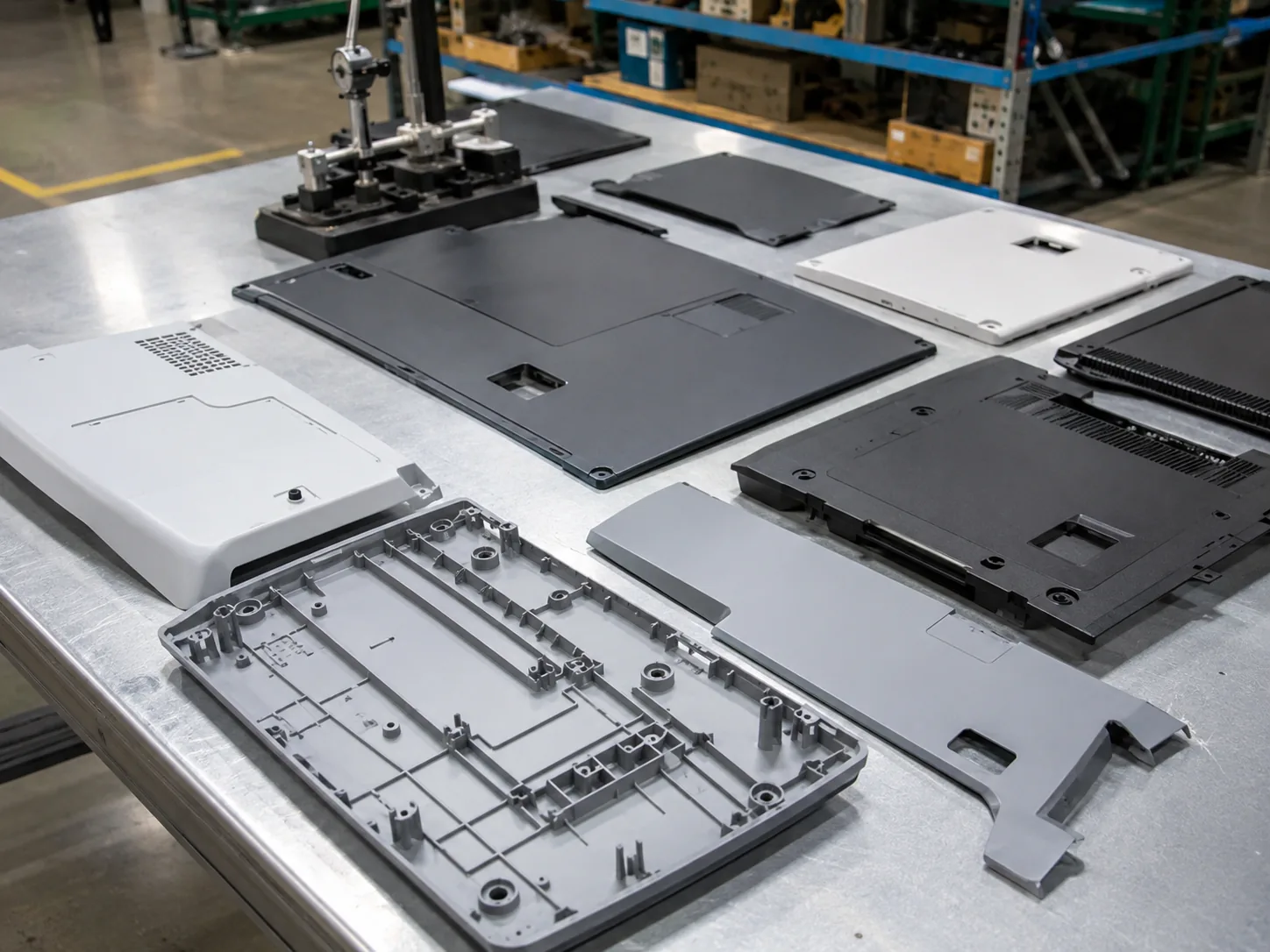
Office Equipment Covers & Panels
Typical Part Features: large flat area, ribs on B-side, structural support
Buyer Concern: warpage control, surface texture, dimensional stability
GBM Review Point: cooling channel design, gate sizing, warpage analysis
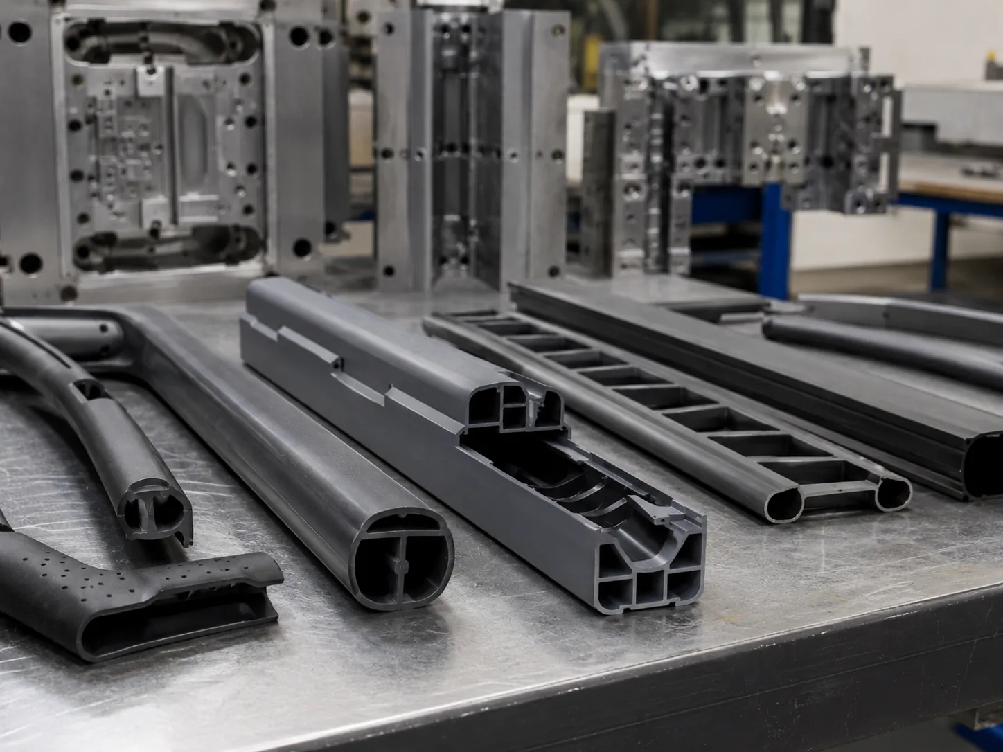
Tubular Shapes & Long Structural Parts
Typical Part Features: hollow section, long flow length, thick wall
Buyer Concern: gas penetration path, stiffness, material use
GBM Review Point: hollow section control, gas delay time, pressure curve
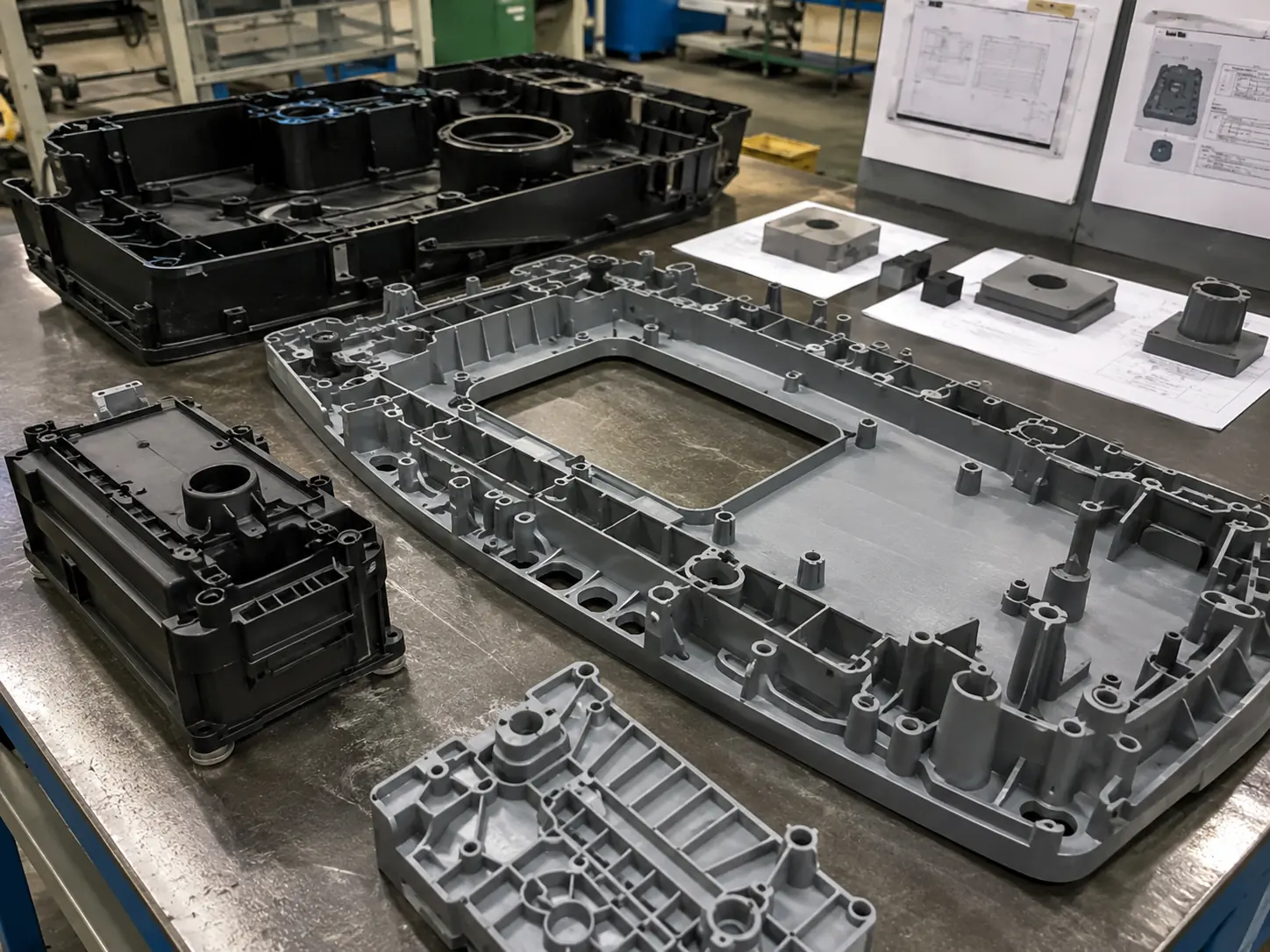
Large Ribbed Frames & Boss-Heavy Parts
Typical Part Features: multiple ribs, heavy bosses, complex structure
Buyer Concern: rib and boss design, T1 adjustment, cooling balance
GBM Review Point: gas channel position, local cooling, flow simulation
Ready to Start Your Gas Assist Molding Project?
Get expert DFM analysis within 24 hours and T1 samples in as fast as 15 days. Contact GBM Mold Technology today for precision you can trust.
Design Considerations for Gas Assist Molded Parts
Gas assist molding is not suitable for every plastic part. GBM Mold reviews geometry, material flow rate, wall thickness, annual quantity and cosmetic requirements before suggesting gas assist tooling.
For some parts, conventional injection molding, structural foam, overmolding, cold runner mold or hot runner mold may be more suitable to achieve the required dimensional tolerance and surface finish.
Check Before Tooling
- Wall thickness: Is there a controlled thick section for gas penetration?
- Gas channel: Does the gas path stay away from thin cosmetic areas?
- Gate position: Does melt flow support the intended gas direction?
- Gas pin / nozzle: Is the gas entry position accessible and stable?
- Venting: Can trapped gas and air escape safely?
- Cooling: Are hollow and solid areas cooled evenly?
- Material: Is the resin flow rate suitable for the selected gas assist strategy?
- T1 validation: Will section cuts, sample weight and dimensions be checked?
Common Gas Assist Injection Molding Defects and Design Causes
| Defect | Possible Design Cause | GBM Trial Check |
|---|---|---|
| Blow-through | Gas pin too close to weak area, thin wall or wrong pressure timing | Check gas pressure, delay time and wall section |
| Gas fingering | Gas enters thin-wall area instead of planned channel | Review gas channel, gate position and flow resistance |
| Short fill | Melt volume, gas timing or channel layout not balanced | Adjust short-shot ratio and filling pattern |
| Sink marks remain | Gas channel not close enough to thick section | Check rib/boss base and gas penetration |
| Surface whitening | Excessive local stress or gas pressure influence | Review A-side surface and packing area |
| Warpage | Uneven cooling or unbalanced gas packing | Check cooling layout and dimensional result |
| Gas trap / burn mark | Poor venting or gas release | Review venting at gas channel end |
Or call us directly at +86 13632611848
Gas Assist Injection Molding vs Conventional Injection Molding
| Item | Gas Assist Injection Molding | Conventional Injection Molding |
|---|---|---|
| Best For | Thick-wall parts, handles, large covers, ribbed structures and cosmetic parts with sink risk. | Solid parts, thin-to-medium wall parts, simpler geometries and lower tooling complexity. |
| Part Weight | May reduce weight where hollow sections are possible. | Usually solid filling unless the part is designed with thinner walls. |
| Sink Mark Control | Can help reduce sink marks near ribs, bosses and thick sections. | Needs careful wall design, packing, cooling and gate control. |
| Tooling Complexity | Requires gas channel, gas pin/nozzle planning and process control. | Usually simpler mold structure for standard parts. |
| Trial Adjustment | Gas delay time, pressure, short-shot ratio and gas penetration need tuning. | Injection speed, packing, cooling and gate balance need tuning. |
| Suitable Buyer | OEMs developing large, thick-wall, cosmetic or structure-integrated plastic parts. | Buyers with standard molded parts where wall thickness and shrinkage are already controlled. |
Need immediate assistance? Call us at +86 13632611848
Gas Assist Mold Manufacturing Support from GBM Mold
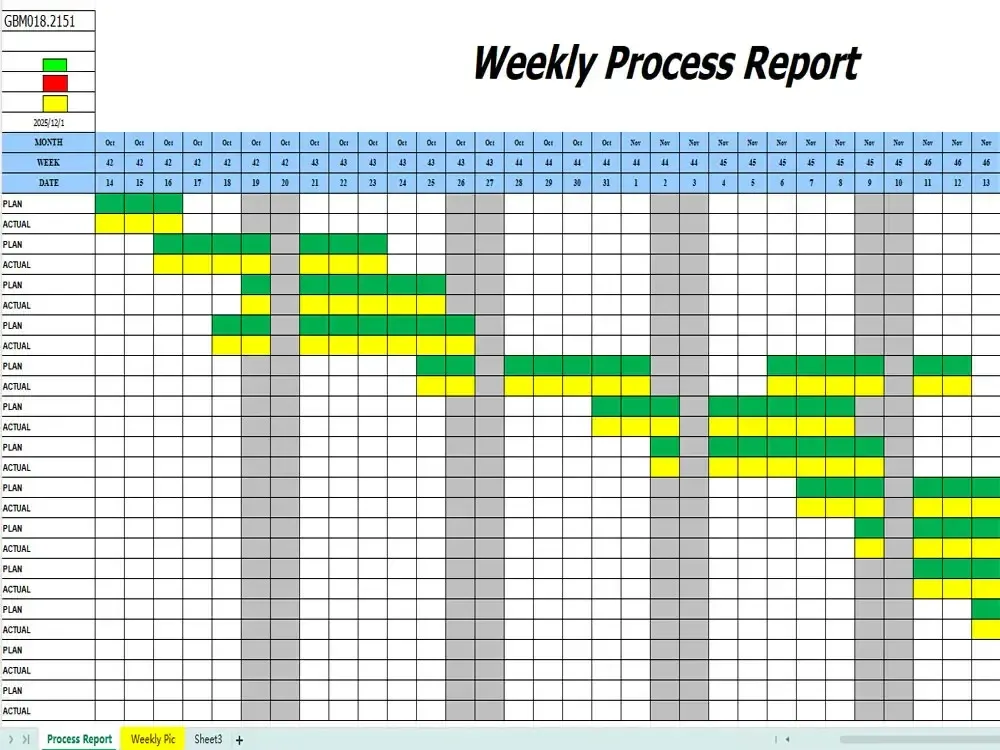
DFM Review Before Mold Cutting
We review part geometry, wall thickness, gas channel feasibility, gate position, gas pin/nozzle location and surface risk before cutting steel.
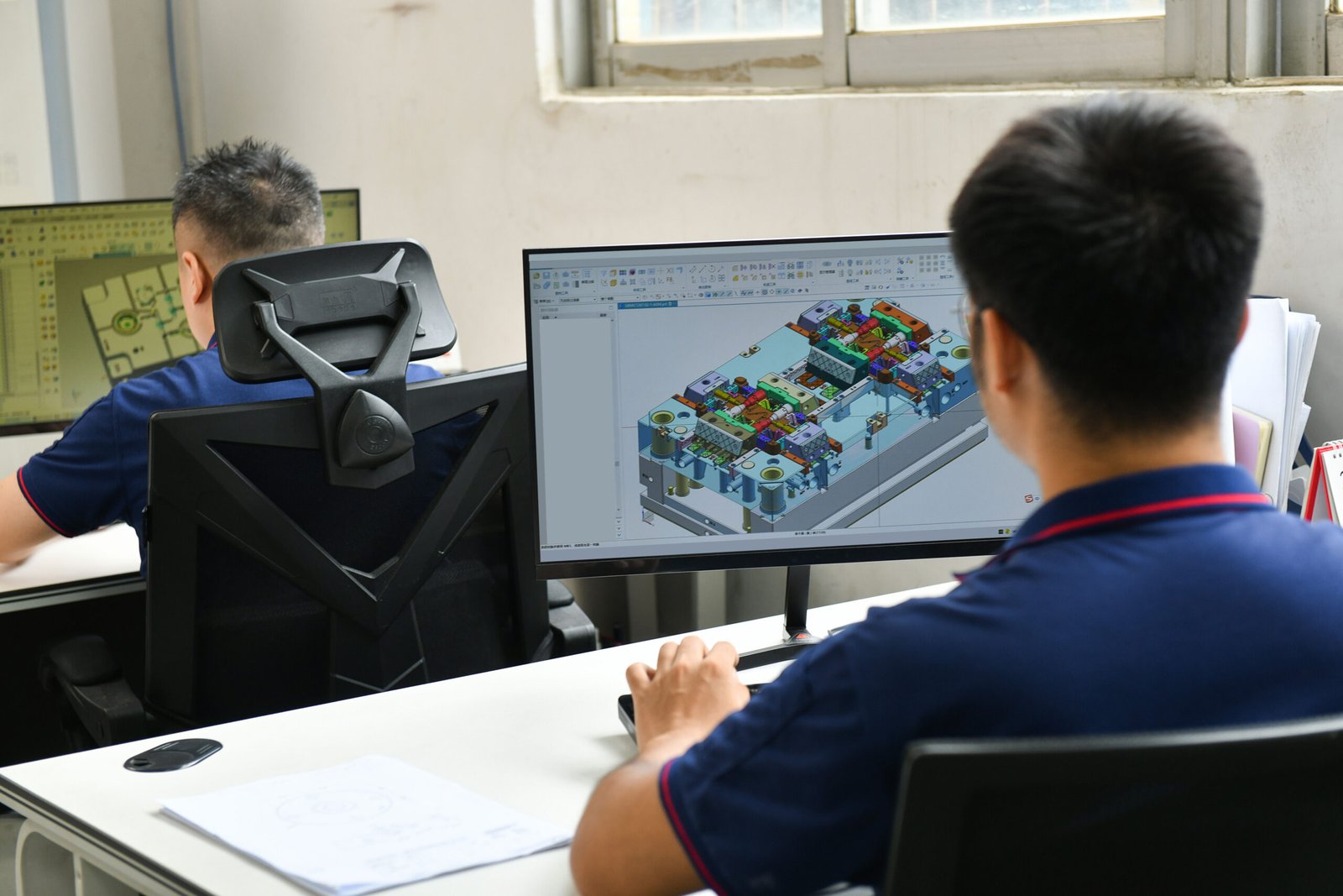
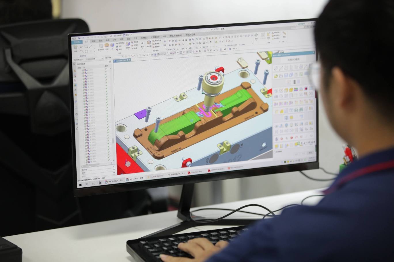
Mold Design and Manufacturing
GBM offers injection mold design, CNC machining, EDM, wire EDM, mold fitting, polishing, cooling layout, and gas-related mold planning.
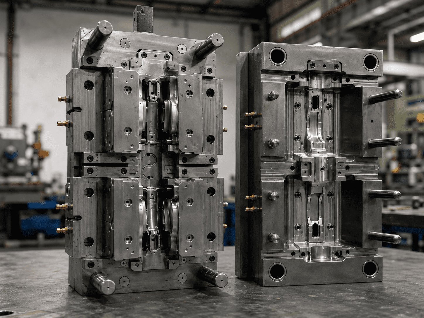
Gas Channel and Trial Adjustment
We check short-shot ratio, gas delay time, gas pressure path, gas penetration result, sink marks and surface condition during T1 trials.
Engineering Plastic Experience
GBM works with common and engineering plastics including ABS, PP, PC, PC/ABS, PA, POM and project-specific resins depending on part requirements.
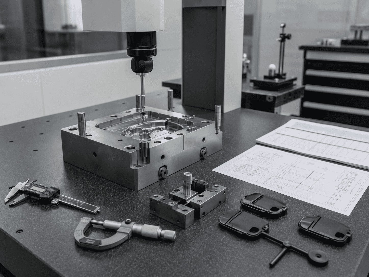
Inspection and Reporting
We can provide T1 samples, sample QC reports, CMM reports, FAI reports and CPK study on request for batch stability verification.
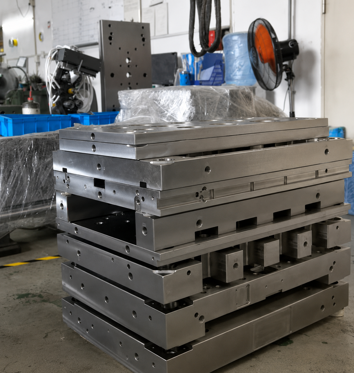
Export Mold Documentation
For export molds, GBM can prepare mold drawings, spare parts list, mold trial video, sample photos, packing photos and maintenance notes.
Or call our engineering team directly: +86 13632611848
What Overseas Buyers Can Check Before Gas Assist Mold Shipment
For overseas gas assist mold projects, GBM prepares visible project evidence before shipment so buyers can review the mold and sample status remotely.
Buyer Check Items & Why It Matters:
-
T1 samples Confirm filling, surface and assembly fit
-
Mold trial video See actual molding and ejection condition
-
Section cut photos Confirm gas channel and hollow structure
-
Sample QC report Check key dimensions before shipment
-
CMM / FAI report Support approval for precision or assembly parts
-
Gas pin / nozzle photos Confirm gas interface position
-
Packing photos Confirm export mold protection
-
Spare parts list Support future mold maintenance
Or call us directly at +86 13632611848
Related Injection Mold and Molding Services
Polycarbonate Injection Molding
For large covers, transparent housings and impact-resistant guards.
ABS Injection Mold
For cosmetic housings, appliance shells and structural covers.
PP Injection Mold Manufacturer
For lightweight molded parts, chemical-resistant covers and living hinges.
Cold Runner Mold
For conventional injection molding projects and standard cost-effective tooling.
Overmolding Mold Manufacturer
For handles, grip parts, soft-touch surfaces and multi-material designs.
High Precision Mold
For tight-tolerance plastic components and detailed CMM inspection parts.
Gas Assist Injection Molding FAQ
What is gas assist injection molding?
How does gas assist injection molding work?
What are the advantages of gas assist injection molding?
How does gas assist injection molding improve part quality?
What are the benefits of gas assist molding compared to traditional injection molding?
What are common applications for gas assist injection molding?
What design considerations are important for gas assist molded parts?
How should gas channels be designed in gas assist molding?
Where should the gas pin or gas nozzle be placed?
What wall thickness is suitable for gas assist injection molding?
What is the difference between internal and external gas assist molding?
Can simulation reduce gas assist molding risk before tooling?
What causes gas fingering in gas assisted injection molding?
What causes blow-through in gas assist molding?
Does GBM offer gas assist injection molding services for US and European buyers?
Does GBM sell gas assist injection molding equipment?
What brands manufacture gas assist injection molding machines or systems?
What information should I send for a gas assist mold quote?
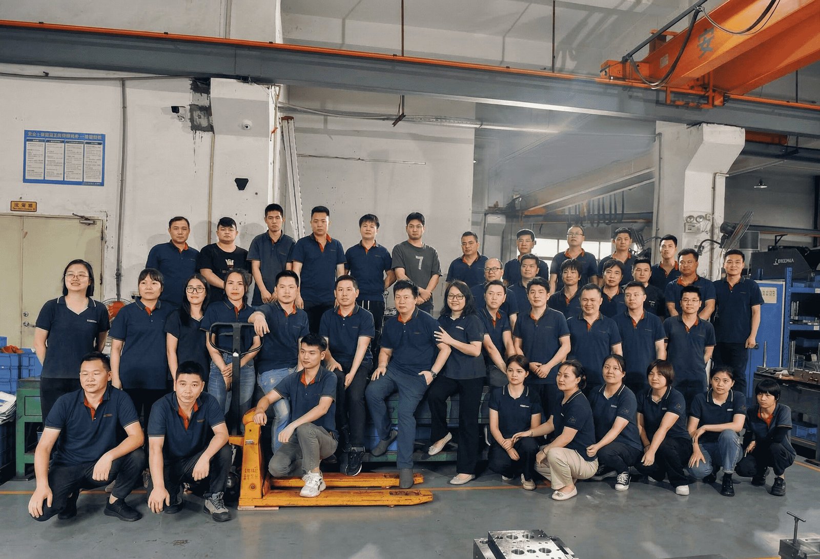
Send Your Gas Assist Injection Molding Project for Review
If your part has thick walls, ribs, bosses, handles, or sink marks, send your drawing to GBM Mold. We’ll review it and suggest practical tooling and molding solutions.