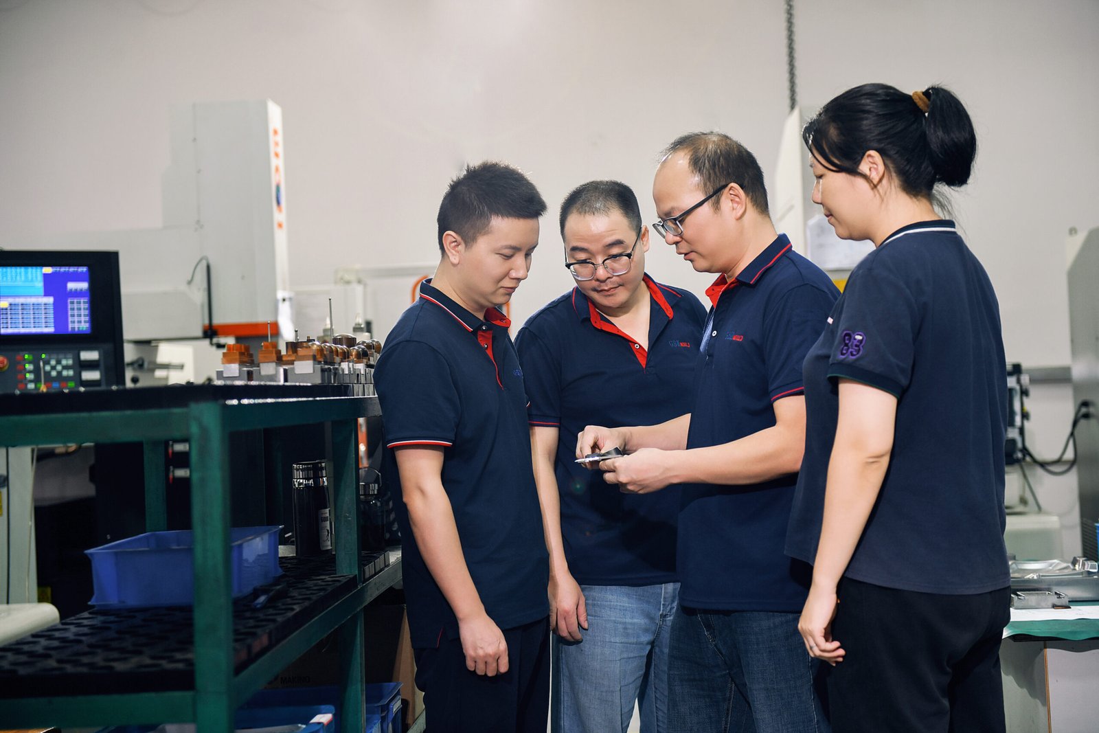
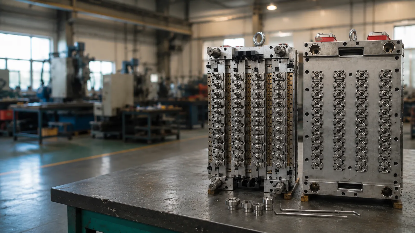
Metal Insert Molding Manufacturer for Custom Plastic Parts
GBM provides custom metal insert molding for threaded inserts, brass nuts, steel pins, sleeves, terminals and stamped metal parts molded into plastic housings, connectors, brackets and industrial components. We support DFM review, insert positioning, mold making, T1 trial, pull-out / torque review and injection molding production.
What Is Metal Insert Molding?
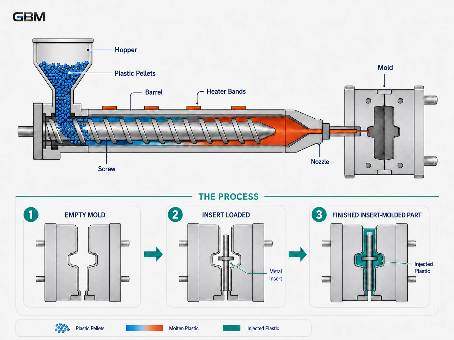
Metal insert molding is a highly efficient manufacturing process where metal components (like threaded brass nuts, stainless steel pins, or electrical terminals) are placed into an injection mold cavity before the plastic is injected. The molten plastic flows around the insert, cooling and solidifying to create a single, strongly bonded, integrated part.
How it differs from other methods:
- • Standard Injection: Only molds plastic. Insert molding combines metal and plastic in one step.
- • Post-Installed Nuts: Pressing or melting nuts in after molding. Insert molding offers superior pull-out and torque strength.
- • Overmolding: Usually refers to molding plastic over plastic, or rubber over plastic. Insert molding specifically refers to encapsulating discrete metal hardware.
When Should You Choose Metal Insert Molding?
Metal insert molding is suitable when a plastic part needs stronger threads, repeated screw assembly, metal contact points, electrical conductivity, shaft support or better wear resistance. It is often used when post-installed inserts may create extra labor, inconsistent insert depth, weak pull-out strength or cracking risk.
However, metal insert molding is not always the best choice for every project. If the order volume is very low, the insert position is not critical, or the product design may still change, heat staking, ultrasonic insertion, press-fit inserts or a prototype trial can be reviewed first.
Advanced Insert Molding
Common Metal Inserts We Mold Into Plastic
We can encapsulate a wide variety of custom and standard metal hardware to meet your mechanical and electrical requirements.
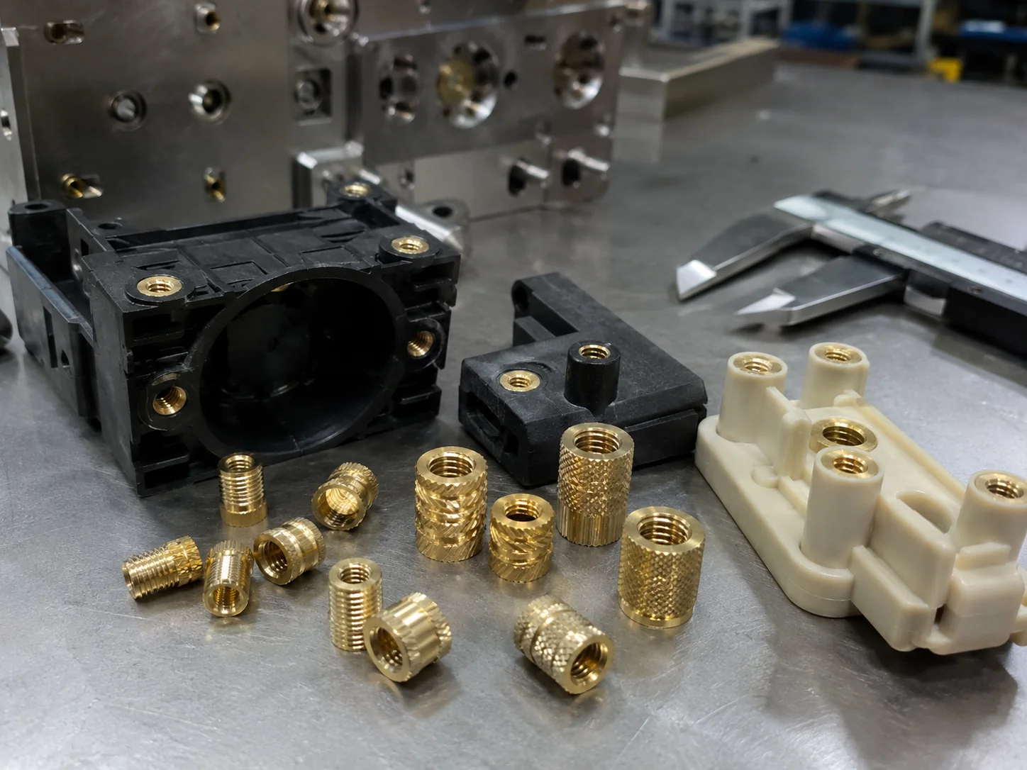
Brass Threaded Inserts
Ideal for repeated assembly. Brass offers excellent thermal conductivity for molding and resists corrosion.
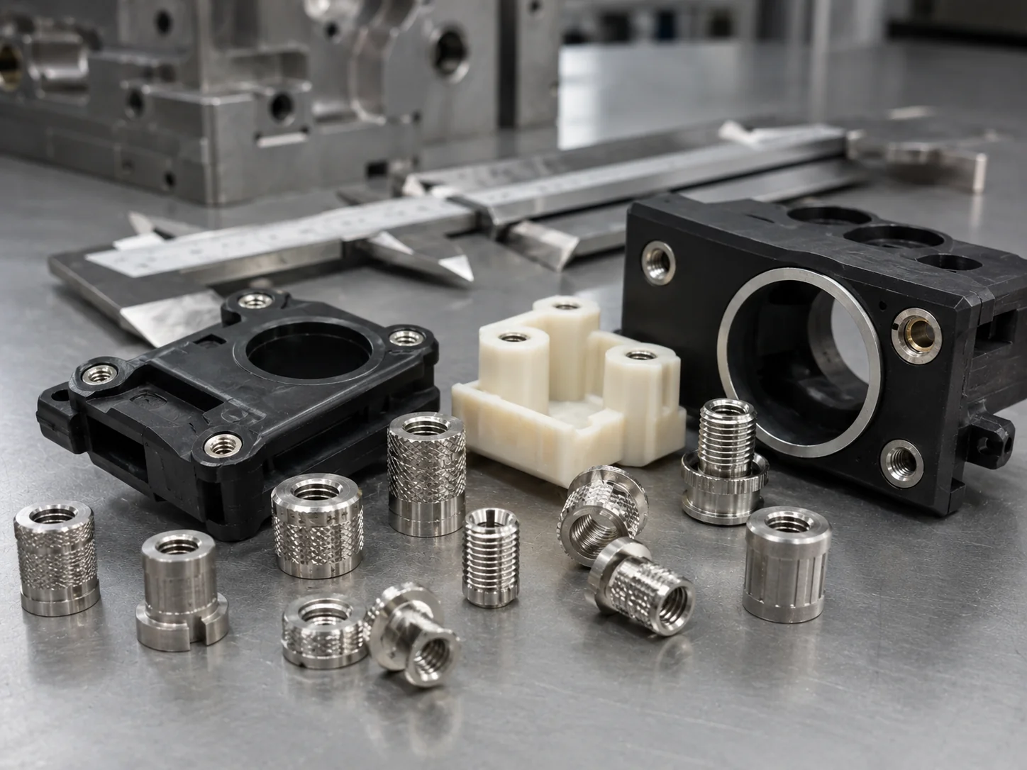
Stainless Steel Inserts
Used for corrosion-resistant, high-strength or harsh-environment applications.
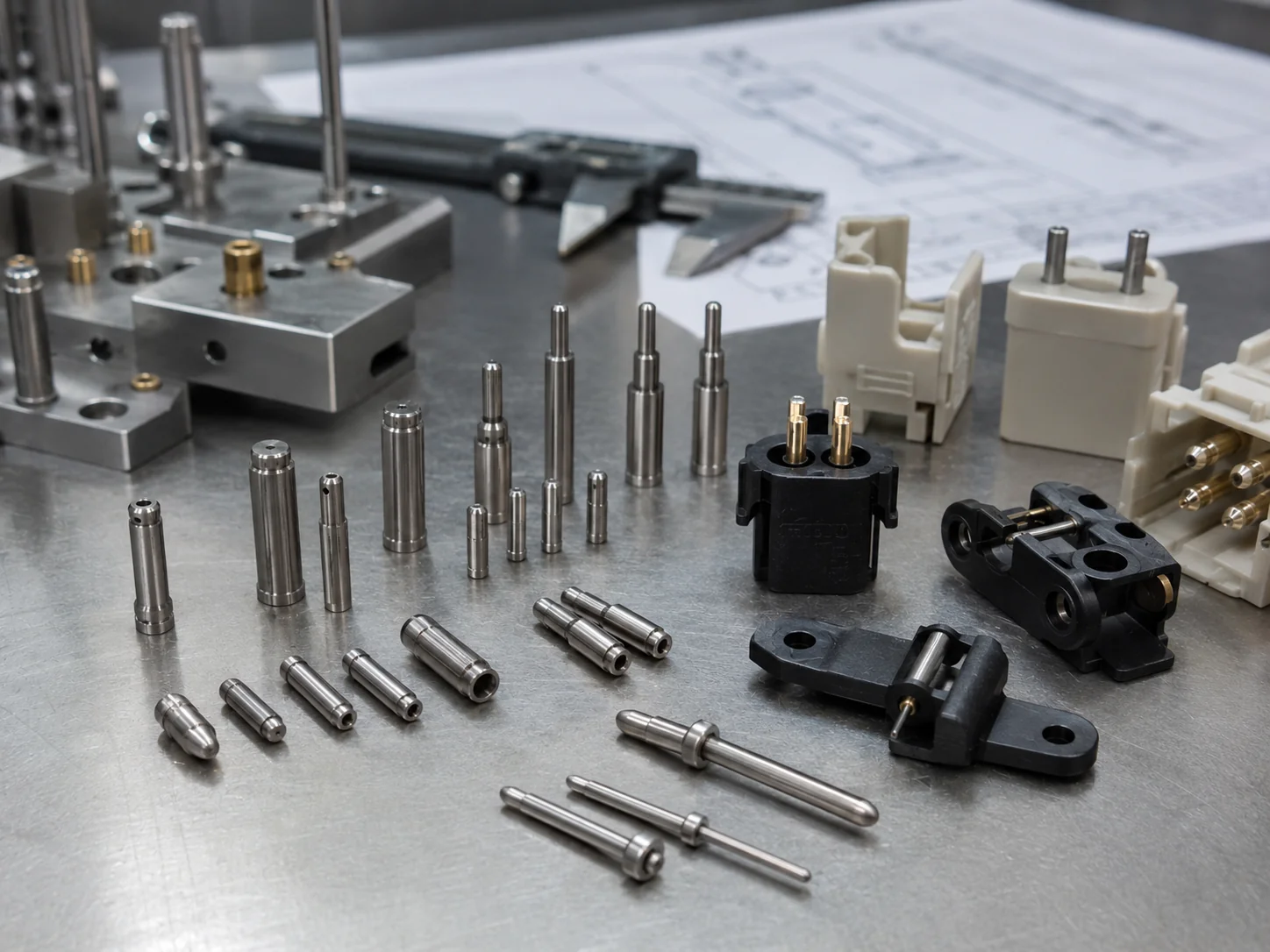
Metal Pins
Commonly used for alignment, hinging, or electrical connection points in electronic housings.
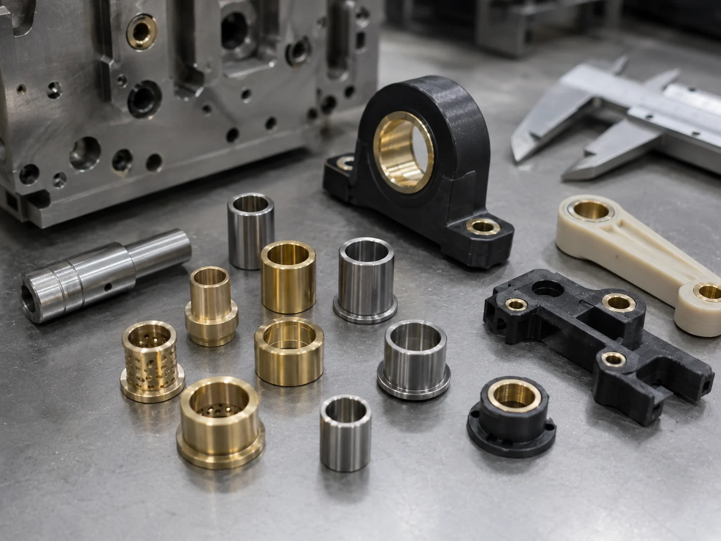
Bushings
Provide wear resistance and structural support for rotating shafts or heavy-load bearing points.
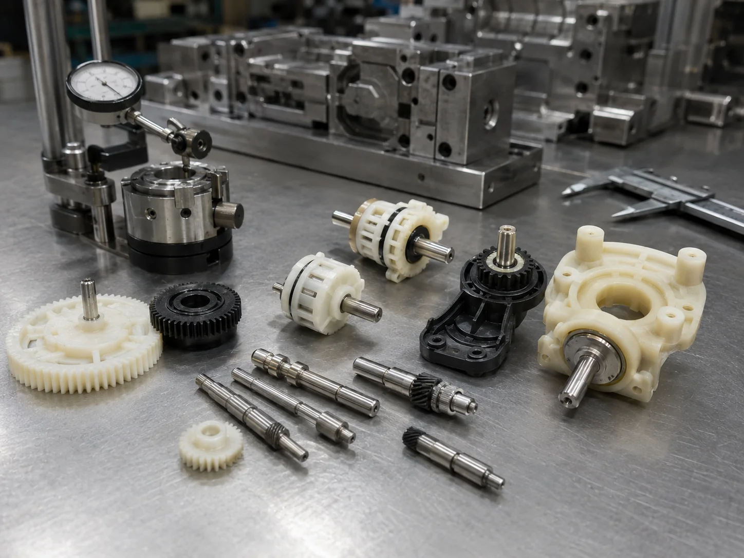
Shafts
Molded directly into gears or rotors, ensuring perfect concentricity and eliminating secondary assembly.
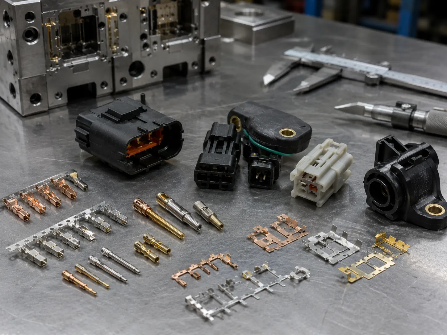
Terminals
Critical for automotive sensors and connectors, providing secure electrical pathways through plastic.
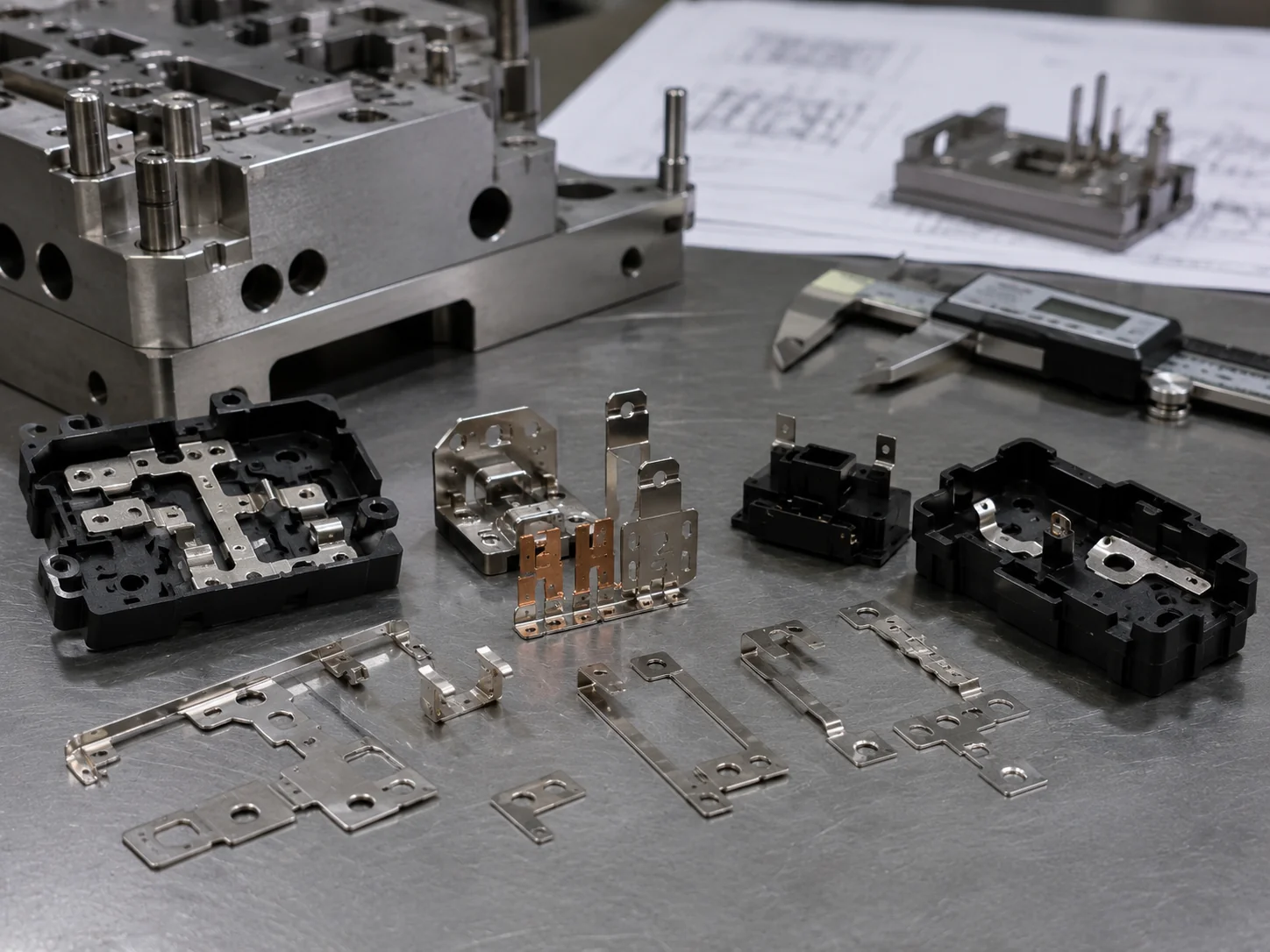
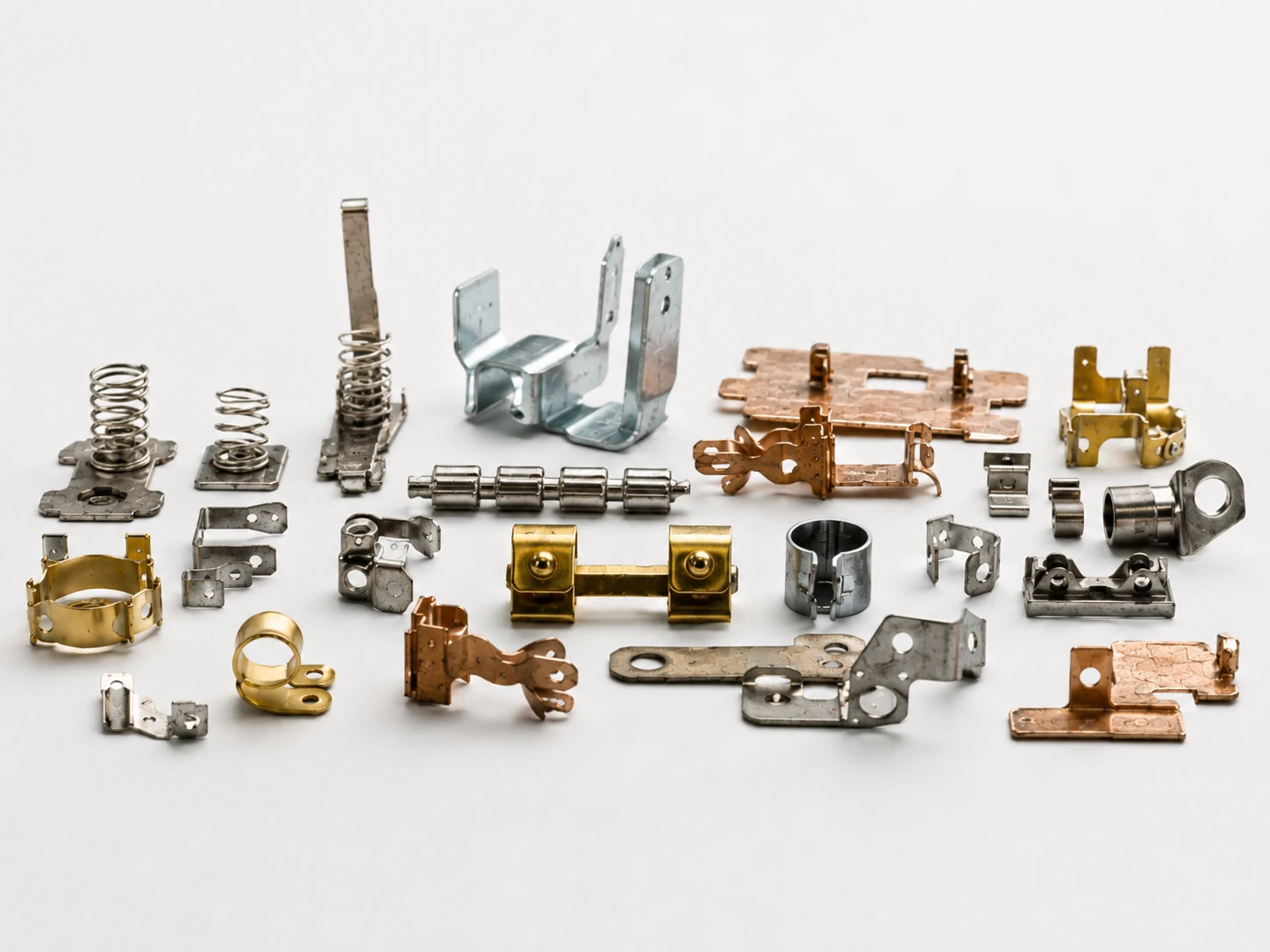
Stamped Metal Parts
Custom stamped brackets or lead frames encapsulated to create complex electromechanical components.
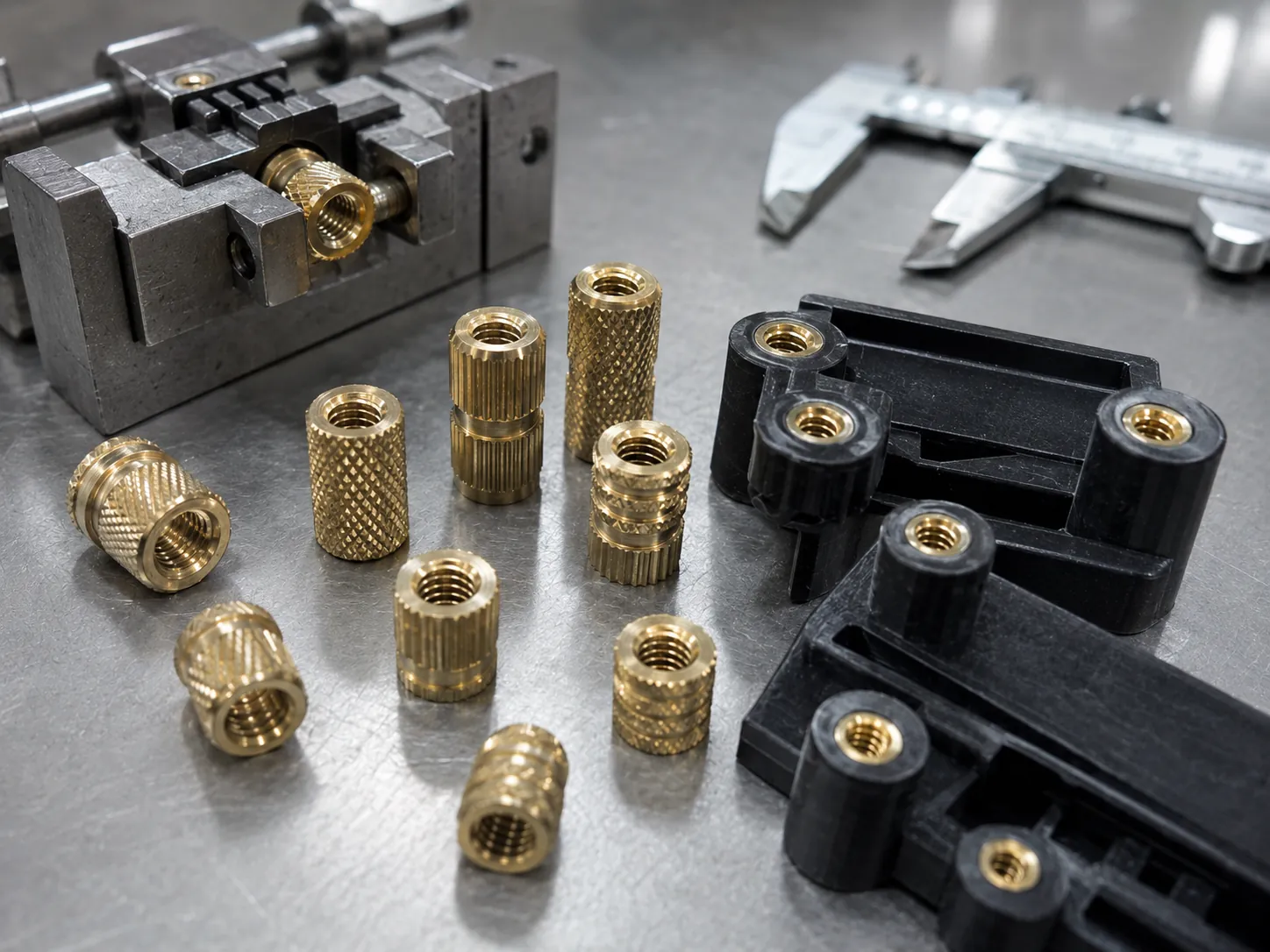
Knurled Inserts
Feature diamond or straight knurling to maximize resistance against pull-out and rotational torque.
Applications of Metal Insert Molded Parts
Our insert molding solutions serve industries that demand uncompromising reliability and performance.
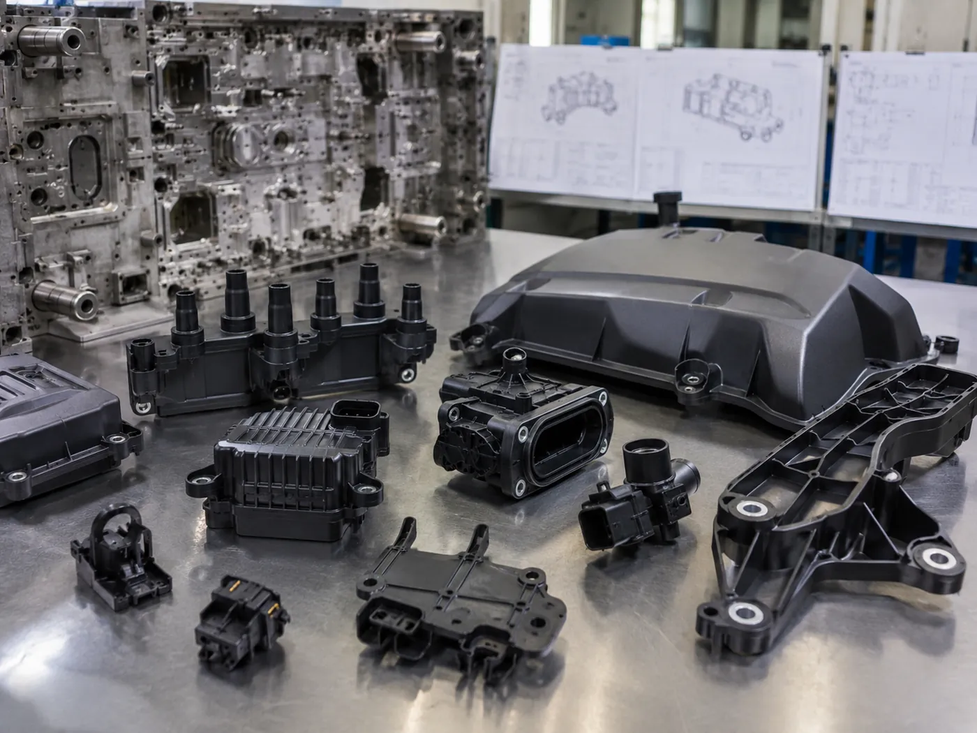
Automotive
Sensors, connector housings, brackets, clips and functional plastic parts with terminals, pins, bushings or threaded inserts.
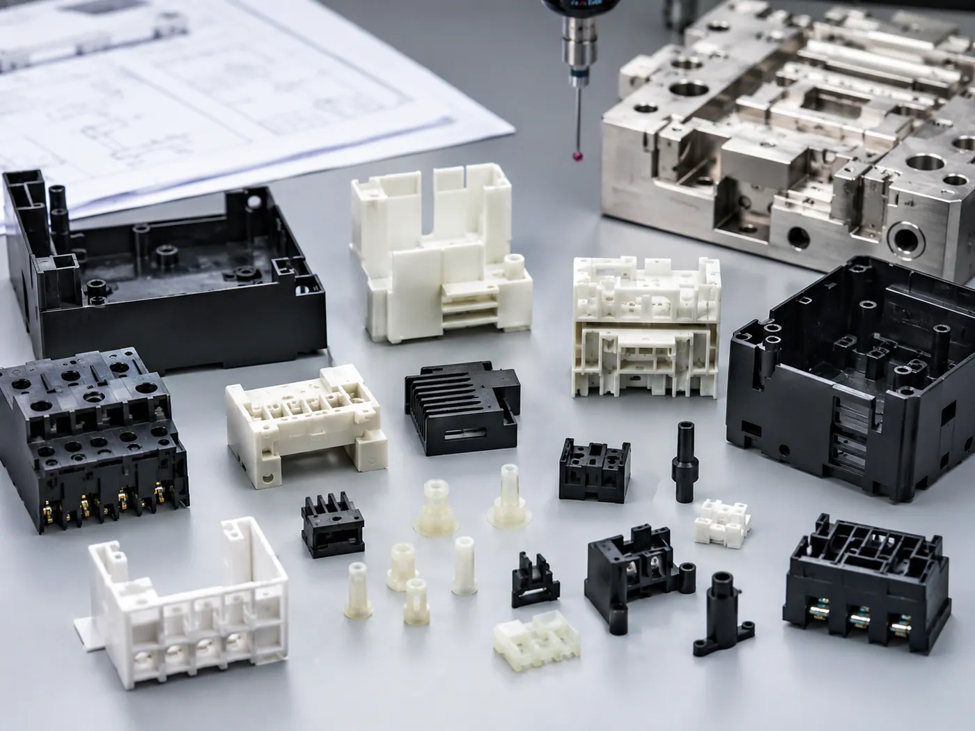
Electronics
Threaded bosses, PCB standoffs, connector bodies, device housings and plastic covers with brass nuts or terminals.
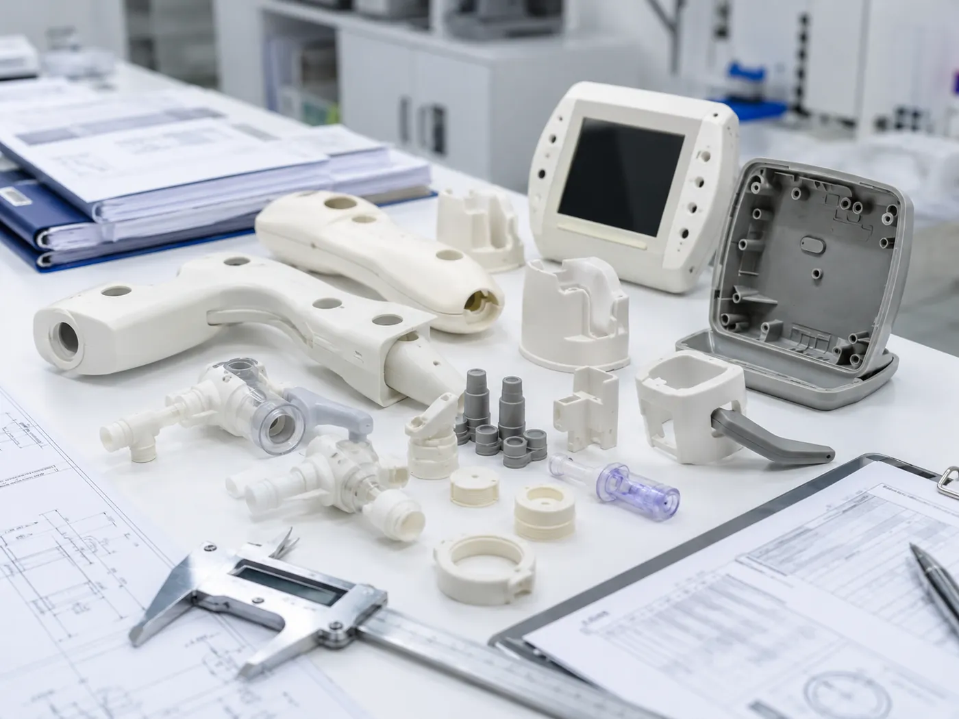
Medical & Precision
Precision housings, covers and fluid-related plastic components where insert position, clean appearance and stable tolerance are important.
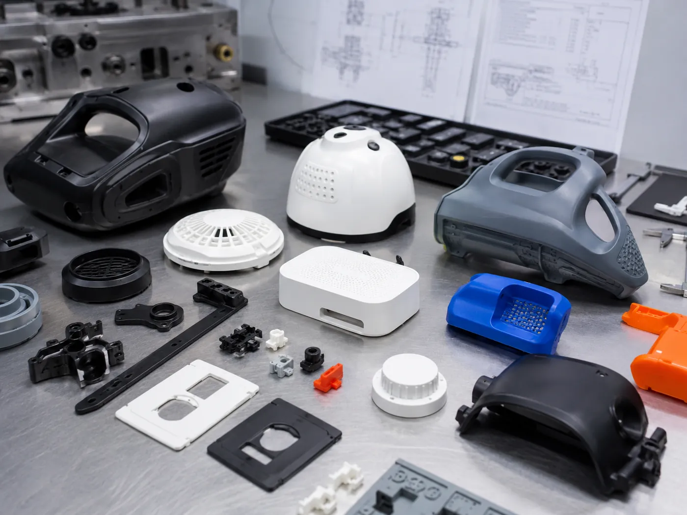
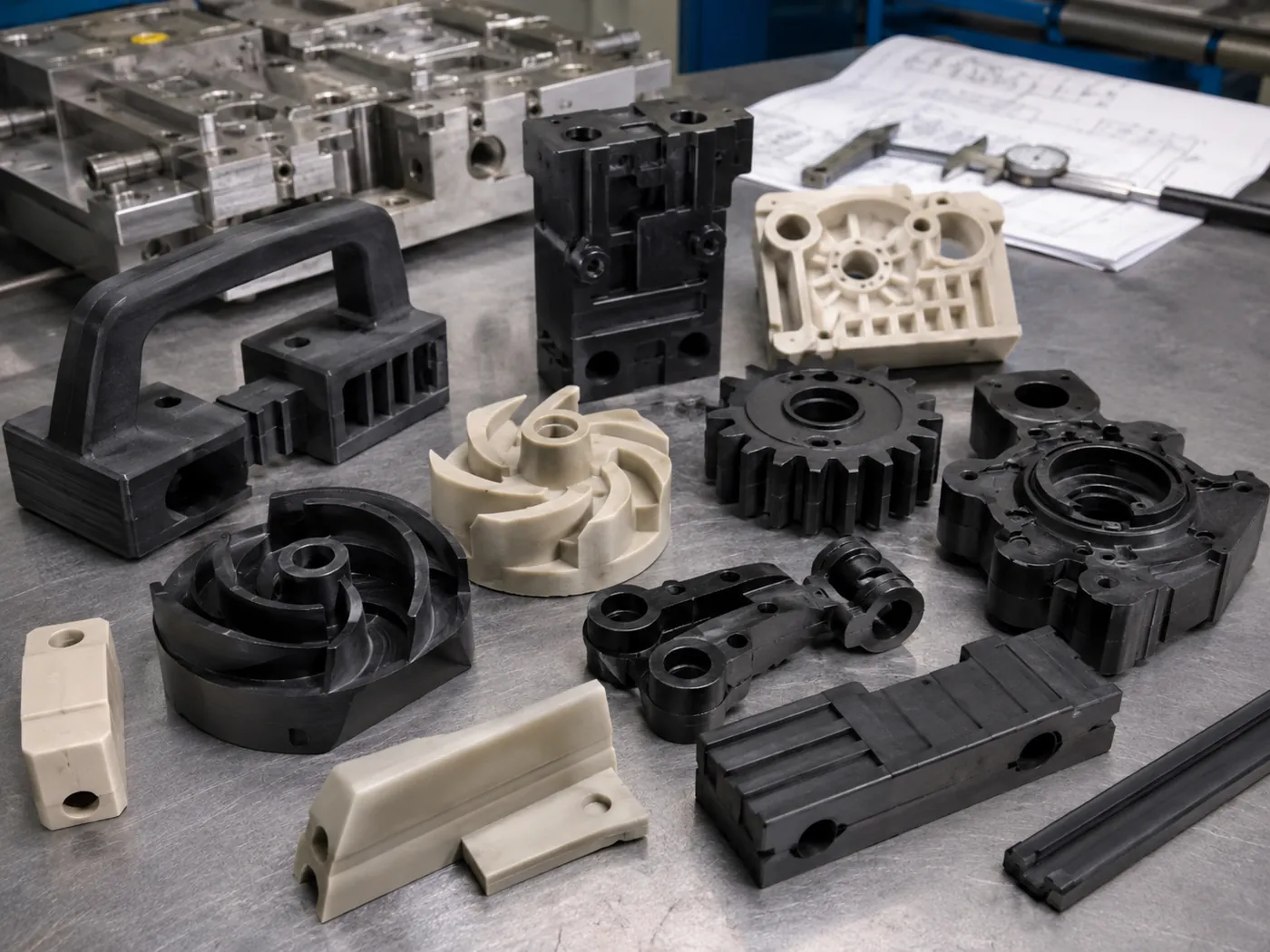
Industrial Equipment
Handles, knobs, pump parts, shaft supports and wear-resistant plastic parts with steel inserts or bushings.
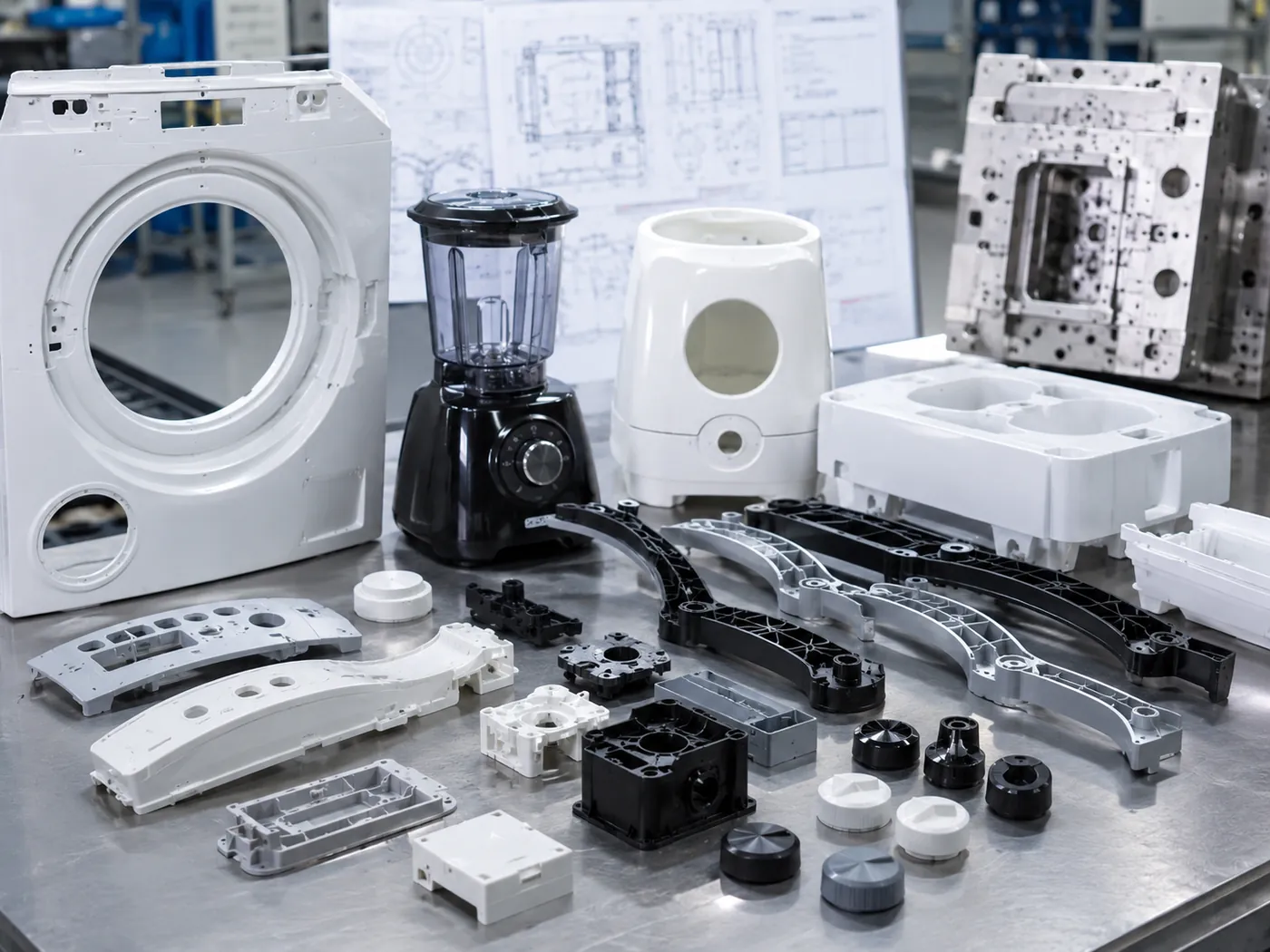
Consumer Products
Durable goods, sports equipment, smart home devices.
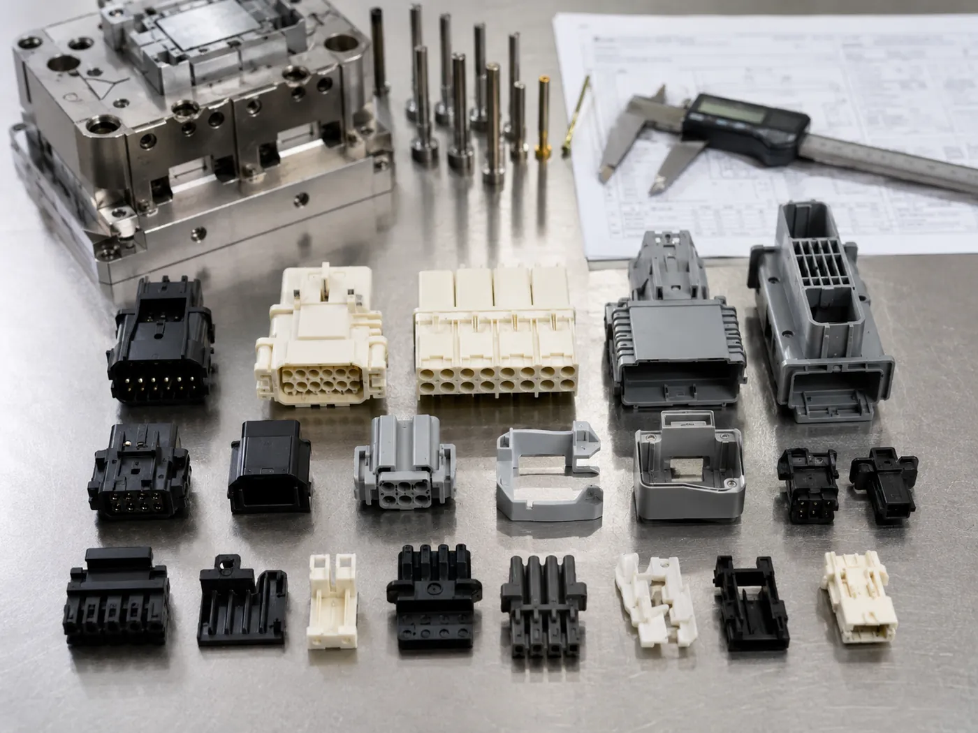
Connectors
Multi-pin connectors, terminal housings and electrical plastic components requiring stable terminal position. Learn more.
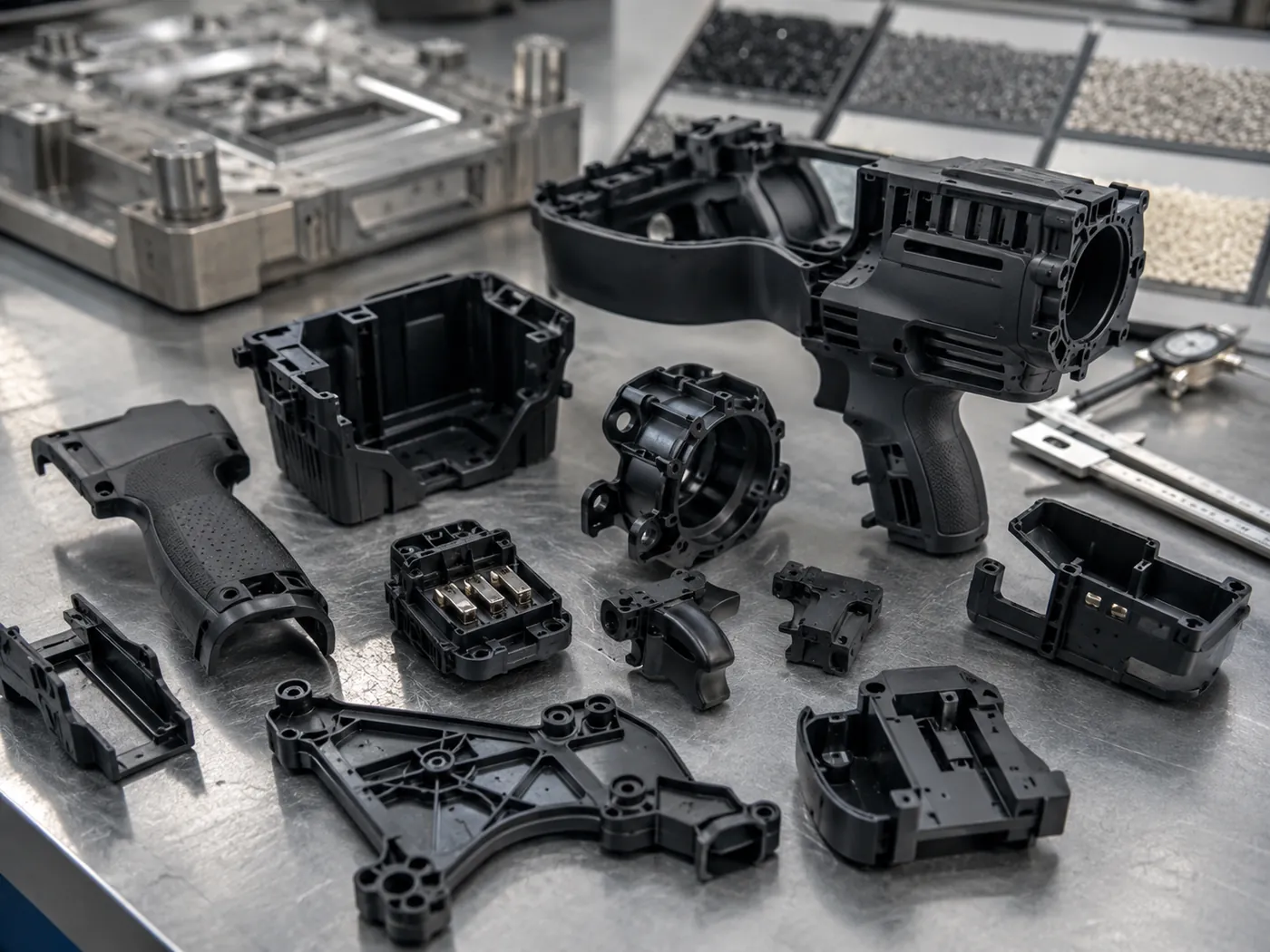
Power Tools
Battery contacts, motor housings, trigger parts and structural components requiring metal reinforcement.
Home Appliances
Knobs, threaded housings, washing machine parts and assembly components with repeated screw fixing.
Why Use Metal Inserts in Plastic Parts?
Plastics are lightweight and moldable, but lack the strength for certain mechanical tasks. Insert molding bridges this gap.
Problem: Plastic thread strips easily
Solution:
A molded-in metal threaded insert provides robust, reusable threads, drastically improving assembly strength and part longevity.
Problem: Plastic boss cracks under load
Solution:
A metal bushing encapsulated in the plastic distributes stress evenly across a wider area, preventing structural failure under compression.
Problem: Need electrical connection
Solution:
Terminal insert molding encapsulates conductive pins directly into the insulating plastic, creating more stable electrical connector structures with molded-in terminal positioning and plastic encapsulation.
Problem: Need repeated screw assembly
Solution:
Unlike self-tapping screws that degrade plastic over time, brass insert molding supports repeated screw assembly better than self-tapping screws in plastic bosses.
Design Guidelines for Metal Insert Molding
Proper Design for Manufacturability (DFM) is critical to prevent part failure, insert shift, or mold damage. The following values are starting references only. Final wall thickness, boss diameter, gate location and insert structure should be confirmed according to plastic material, insert size, knurl design, load direction, shrinkage and assembly requirements.
Wall Thickness
As a starting reference, enough plastic wall thickness should be kept around the insert to reduce hoop stress and cracking risk. The final wall thickness should be confirmed according to insert size, resin shrinkage, boss structure and load direction.
Insert Position
Avoid placing inserts too close to the edge of the part. Maintain adequate distance to prevent short shots or weak edges.
Knurling / Undercuts
Use diamond knurling for resistance to both pull-out and rotational torque. Add undercuts for extra pull-out strength.
Boss Design
The boss outer diameter is usually reviewed together with insert diameter, thread depth, screw load and resin toughness. For brittle or high-shrinkage materials, additional wall thickness or structure changes may be needed.
Avoid Sharp Corners
Sharp corners on the metal insert create high stress concentrations in the cooling plastic. Use radiused edges where possible.
Gate Location
Do not gate directly onto the insert. Position gates to allow plastic to flow evenly around the insert, minimizing core shift.
Weld Line Risk
Plastic flowing around an insert creates a weld line on the far side. Design the part so this weld line is not in a high-stress area.
Hole Depth
For blind threaded inserts, ensure the plastic does not flow into the threads. A precise mold pin is required to seal the hole.
Get a free 24H DFM analysis for your insert molding project.
Insert Positioning and Mold Structure
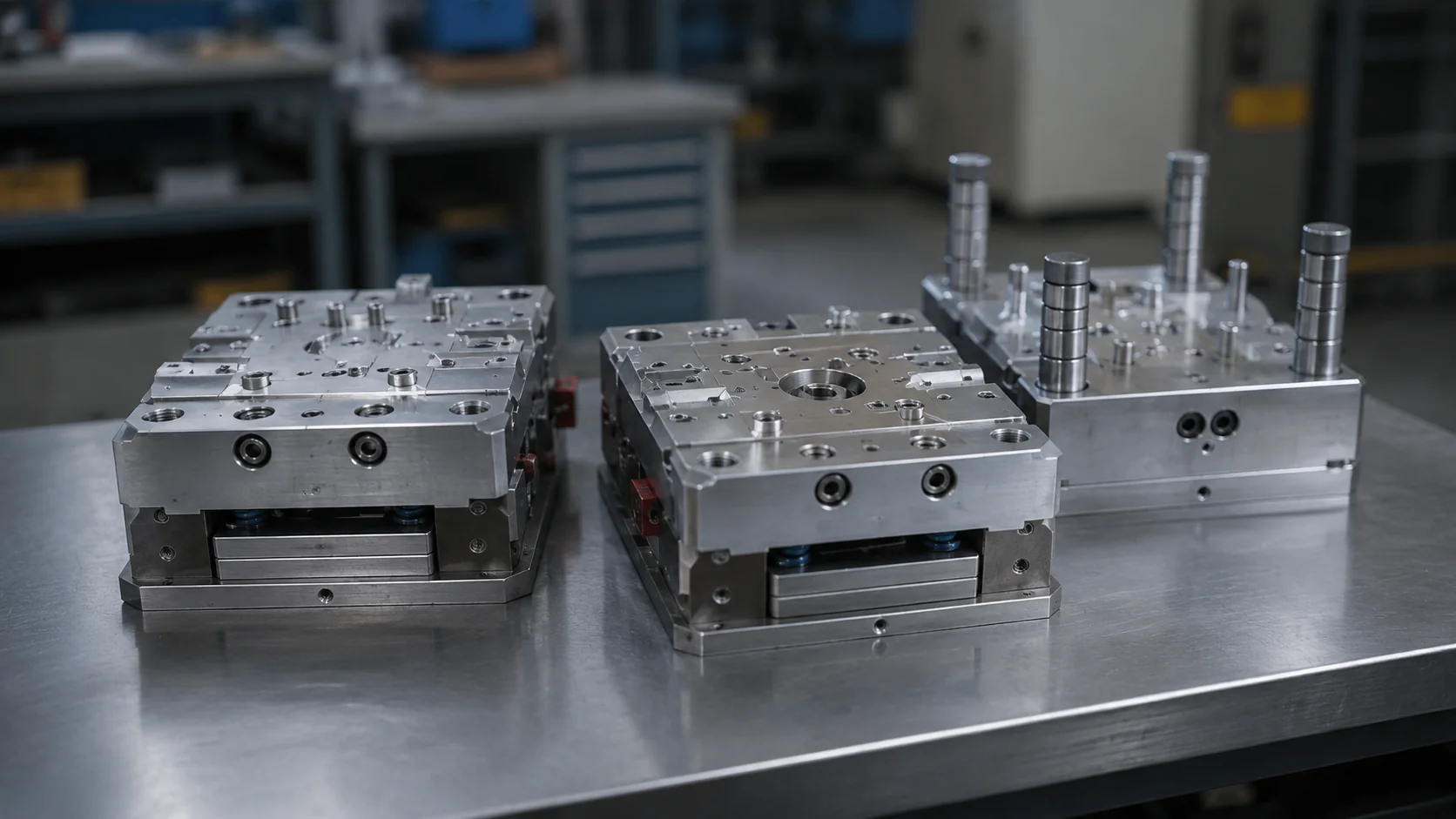
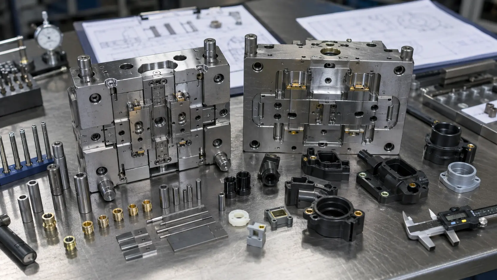
The biggest challenge in insert molding is keeping the metal piece exactly in place while high-pressure plastic is injected. GBM uses locating pins, insert pockets, magnetic holding options, gate review and T1 trial correction to reduce insert shift risk during molding. We rely on precision core pins and insert positioning to secure the hardware.
-
Precision Locating Pins
Custom-machined core pins hold threaded inserts securely by their internal threads, preventing tilt and sealing plastic out.
-
Magnetic Holding
For ferrous metal inserts (like steel), we integrate high-temp magnets into the mold cavity to hold flat parts flush against the mold wall.
-
Vertical Injection Molding
We heavily utilize vertical injection molding machines. Gravity naturally keeps the inserts seated in the lower mold half during the clamping and injection phase.
Common Metal Insert Molding Defects and Solutions
Metal insert molding has more risk points than standard injection molding because the insert position, insert tolerance, plastic shrinkage, gate location and mold shut-off area all affect final part quality. GBM reviews these risks before tooling and during T1 trial to reduce insert shift, cracking, thread flash and weak pull-out strength.
| Defect | Common Cause | GBM Control Method |
|---|---|---|
| Insert shift or tilt | High injection pressure, weak insert holding, poor locating pin fit | Review gate direction, use locating pins or insert pockets, check T1 sample position |
| Plastic cracking around insert | High shrinkage stress, sharp insert edges, insufficient boss wall | Adjust wall thickness, add radius, review material toughness and insert pre-heating |
| Poor pull-out strength | Shallow knurling, insufficient plastic fill, weak boss structure | Review knurl depth, undercut design, gate location and packing condition |
| Poor torque resistance | Straight knurl only, insufficient anti-rotation feature | Use diamond, cross or hex knurling when suitable |
| Flash inside thread | Worn core pin, loose insert ID tolerance, poor shut-off | Improve core pin fit, check insert tolerance and inspect thread with Go/No-Go gauge |
| Sink mark opposite insert | Excess plastic mass around boss | Core out thick sections and adjust holding pressure / cooling time |
| Weld line weakness | Flow fronts meet behind the insert | Move gate position or adjust flow direction during DFM |
Pull-Out Strength and Torque-Out Review
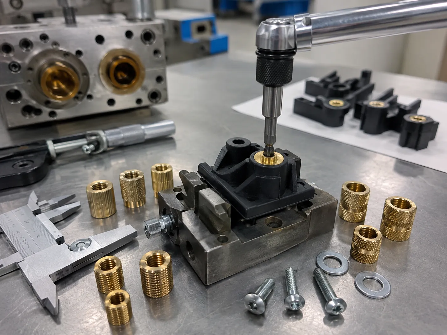
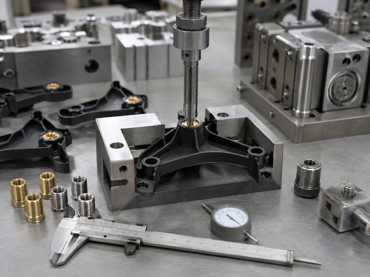
A metal insert molded part should not be judged only by appearance. For threaded inserts, bushings, terminals and shafts, pull-out force and torque-out resistance may need to be checked according to the assembly load, screw size and application environment.
Pull-Out Force
Pull-out force measures the axial load required to pull the insert out of the plastic boss. It is affected by insert undercut geometry, knurl depth, plastic material, boss wall thickness and molding condition.
Torque-Out Resistance
Torque-out resistance measures the rotational force required to turn the insert inside the plastic. It is affected by knurl pattern, insert diameter, plastic fill around the insert and boss strength.
Testing Note: GBM can support pull-out and torque-out sample review according to project requirements. For critical parts, the required force value, screw type, torque value and test method should be confirmed before mold making.
Pull-Out / Torque Review Available
T1 Sample Review and Trial Feedback
Plastic Materials for Metal Insert Molding
Selecting the right thermoplastic is crucial for managing shrinkage around the insert and preventing cracking.
| Material | Suitable Insert Scenarios | Considerations & Risks |
|---|---|---|
| PA6 / PA66 (Nylon) | Gears, automotive under-hood parts, power tools. Excellent toughness and wear resistance. | High shrinkage rate. Risk of cracking if wall thickness around insert is insufficient. Inserts may need pre-heating. |
| PPS | Automotive sensors, high-temp electrical connectors. Outstanding heat and chemical resistance. | Brittle material. Requires careful design of insert knurling to avoid sharp corners that cause stress concentrations. |
| PBT | Electrical housings, switches. Good dimensional stability and electrical insulation. | Prone to warpage. Gate location relative to the insert is critical to manage flow lines. |
| PC (Polycarbonate) | Precision housings, clear covers and impact-resistant plastic parts. | PC has stress cracking risk around metal inserts, so wall thickness, insert edge radius, material grade and possible insert pre-heating should be reviewed. |
| ABS | Consumer electronics, appliances. Good impact strength and surface finish. | Generally forgiving, but poor weld line strength. Avoid placing gates where flow fronts meet at the insert. |
| PP (Polypropylene) | Living hinges, chemical containers, low-cost consumer goods. | High shrinkage can cause sink marks opposite the insert. Low pull-out strength compared to engineering resins. |
| PC-ABS | Automotive interior components, robust electronic housings. | Balances PC toughness with ABS processability. Moderate risk of stress cracking. |
| POM (Delrin/Acetal) | Precision gears, bearings, sliding mechanisms. Low friction. | High shrinkage. Requires robust mechanical interlocking (deep knurls) as it does not bond well chemically. |
Metal Insert Molding vs Post-Installed Inserts
While post-installation methods exist, molded-in inserts offer superior mechanical properties and consistency for mass production.
| Installation Method | Process | Strength Review | Production Notes |
|---|---|---|---|
| Molded-in metal inserts | Inserts are placed into the mold before injection | Usually stronger when insert geometry and plastic fill are correct | No secondary insertion step, but loading time and mold structure are more complex |
| Heat staking inserts | Heated insert is pressed into molded hole | Good for many applications | Requires secondary equipment and process control |
| Ultrasonic inserts | Ultrasonic vibration melts plastic around insert | Good when boss design is suitable | Requires ultrasonic equipment and stable insert depth control |
| Press-fit inserts | Insert is pressed into molded hole | Depends heavily on boss design and material toughness | Fast, but cracking risk should be reviewed |
| Self-tapping screws | Screw cuts into plastic boss | Suitable for lower-load or limited assembly | Plastic thread may wear after repeated assembly |
Metal Insert Molding vs. Overmolding
While the terms are sometimes used interchangeably, in precision manufacturing, they refer to distinctly different processes.
Metal Insert Molding
Formula: Pre-manufactured Metal Part + Plastic Injection.
Focuses on embedding discrete metal hardware (nuts, pins, stamped parts) into a plastic host to provide mechanical strength or electrical conductivity.
Overmolding
Formula: Plastic over Plastic / Rubber over Plastic / Plastic over large Metal Substrate.
Focuses on adding a soft grip (TPE/TPU) to a rigid plastic part, or combining two colors/materials. Learn more at our Overmolding Mold Manufacturer page.
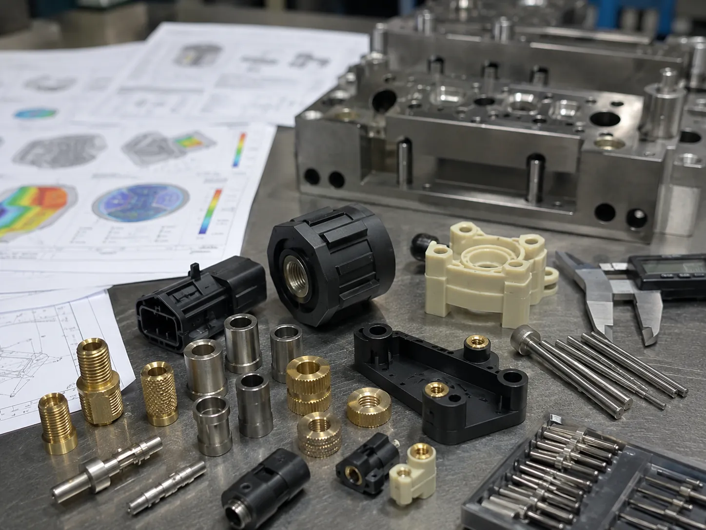
DFM Review Before Metal Insert Mold Making
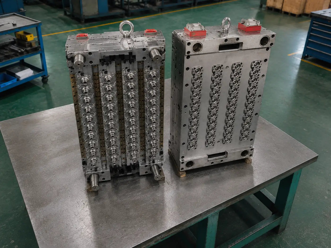
Before cutting any steel, our engineering team conducts a comprehensive Design for Manufacturability (DFM) analysis to identify potential risks.
- Insert drawing & tolerance verification
- Plastic wall thickness analysis
- Material compatibility check
- Mold loading method simulation
- Gate location & mold flow analysis
Metal Insert Mold Manufacturing Process
From initial inquiry to final delivery, our streamlined process ensures quality and speed.
Inquiry & Review
DFM & Design
Steel Machining
T1 Samples
Mass Production
QC & Delivery
Production Options: Scalable to Your Volume
We tailor the insert loading method to balance your tooling budget with unit costs based on annual volume.
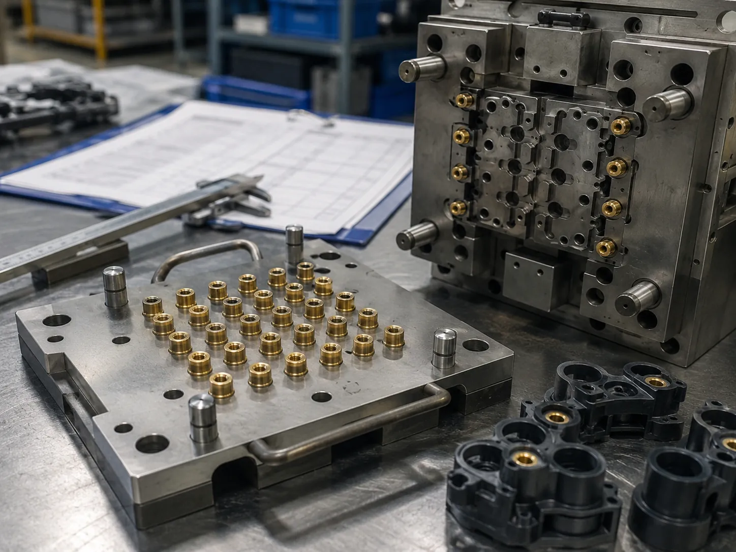
Low Volume
Manual Insert Loading
Suitable for prototype, trial production and small-batch projects. Manual loading keeps tooling investment lower, but unit cost and cycle time are higher.
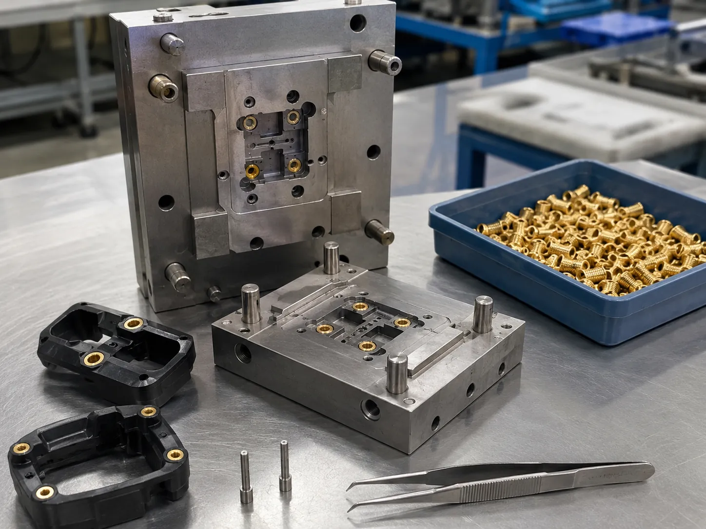
Medium Volume
Fixture-Assisted Loading
Suitable when the project needs better loading consistency but full automation is not yet justified. Custom jigs, trays or pre-loading plates can help reduce operator variation.
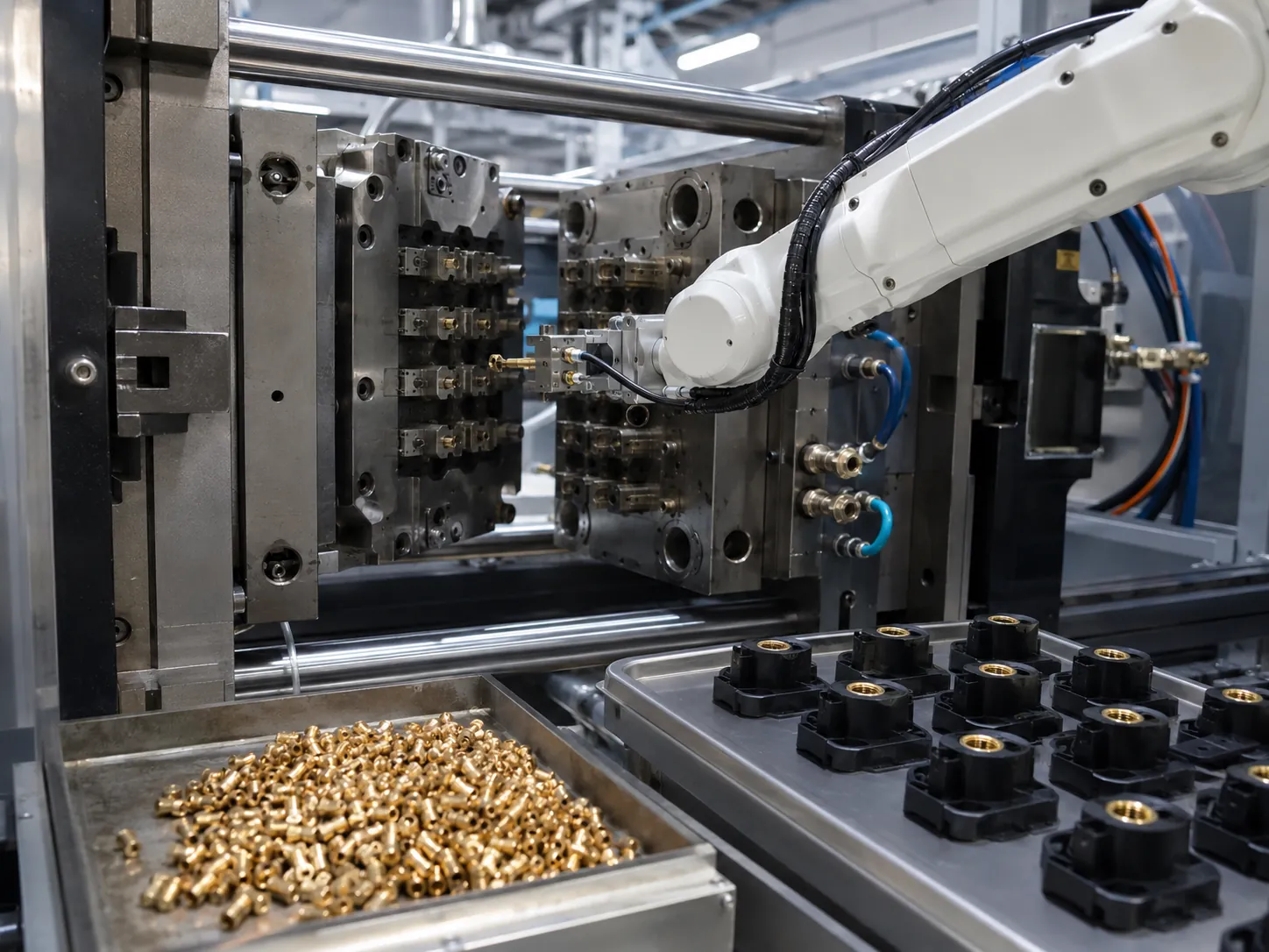
High Volume
Robotic Automation
Suitable for stable high-volume insert molded parts production where annual demand can justify the automation cost. Automation can improve loading speed and consistency, but it increases initial fixture and system investment.
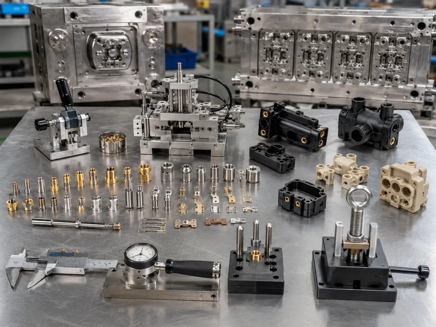
Quality Control for Metal Insert Molded Parts
Insert molding introduces unique quality risks. GBM employs a strict QC protocol specifically designed for metal-plastic assemblies.
Cost Factors of Metal Insert Molding
Metal insert molding cost is affected by both the plastic part and the metal insert. A low-cost brass nut project can still become expensive if there are many inserts per part, strict thread sealing requirements, high labor loading time or special pull-out testing requirements.
| Cost Factor | Why It Affects Cost |
|---|---|
| Insert material | Brass nuts are usually simpler; stainless steel, copper terminals or custom machined inserts increase cost. |
| Insert tolerance | Loose insert tolerance may cause flash, tilt, thread sealing problems or unstable positioning. |
| Number of inserts per part | More inserts increase loading time, fixture complexity and inspection work. |
| Insert loading method | Manual loading reduces initial tooling cost; automation improves unit cost for high-volume production. |
| Mold cavity number | More cavities increase mold cost but may reduce unit price when annual volume is high enough. Multi-cavity insert molding is ideal for mass production. |
| Thread protection | Core pins, shut-off areas and insert sealing details increase tooling precision requirements. |
| Pull-out / torque testing | Mechanical testing adds QC work but helps verify assembly strength. |
| Plastic material | PPS, PA-GF, PEEK and brittle materials need stricter temperature, shrinkage and stress control. |
Metal Insert Molding Project Examples
Real-world solutions engineered by GBM for global clients.
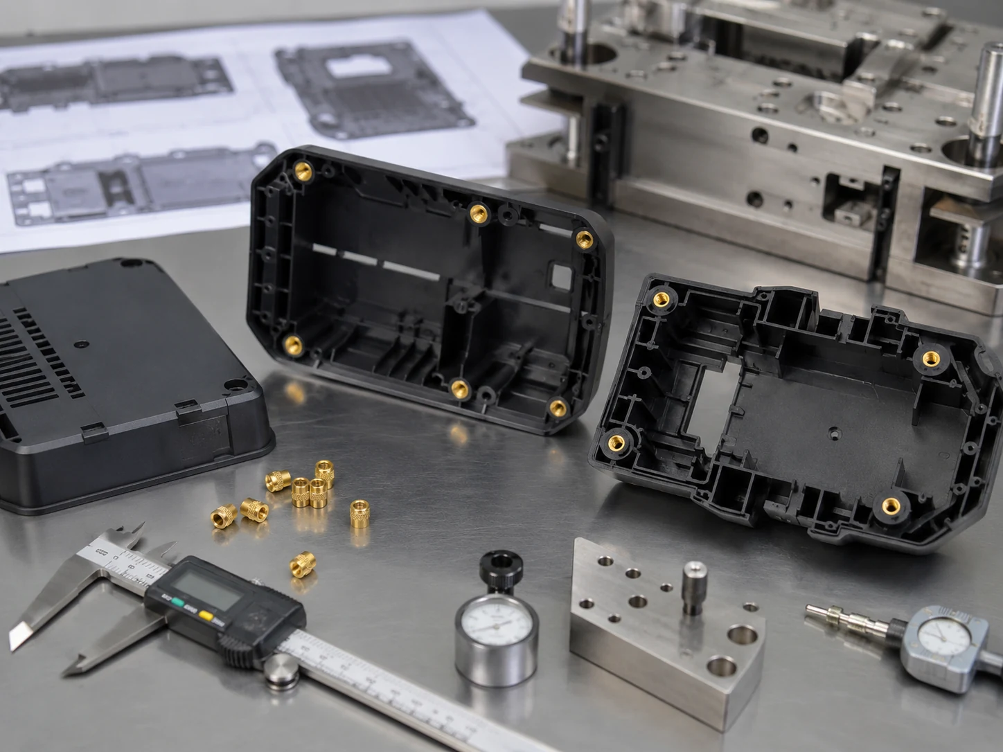
Electronic Housing
Material: PC+ABS
Insert: 4x Brass M3 Nuts
Challenge: Preventing plastic flashing into internal threads.
Solution: Stepped core pins and thread shut-off review to reduce plastic flash inside internal threads. Suitable for PC+ABS electronic housing.
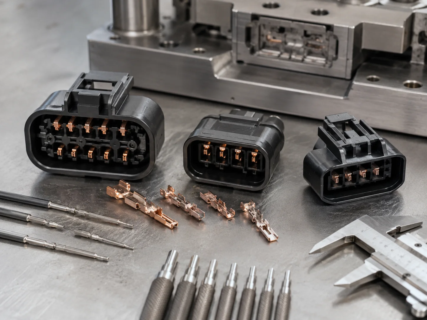
Auto Sensor Connector
Material: PPS
Insert: 6x Copper Terminals
Challenge: Terminals bending during injection pressure.
Solution: Multi-point gating to balance melt flow pressure. Suitable for PPS terminal insert molding where terminal position and flow pressure balance are important.
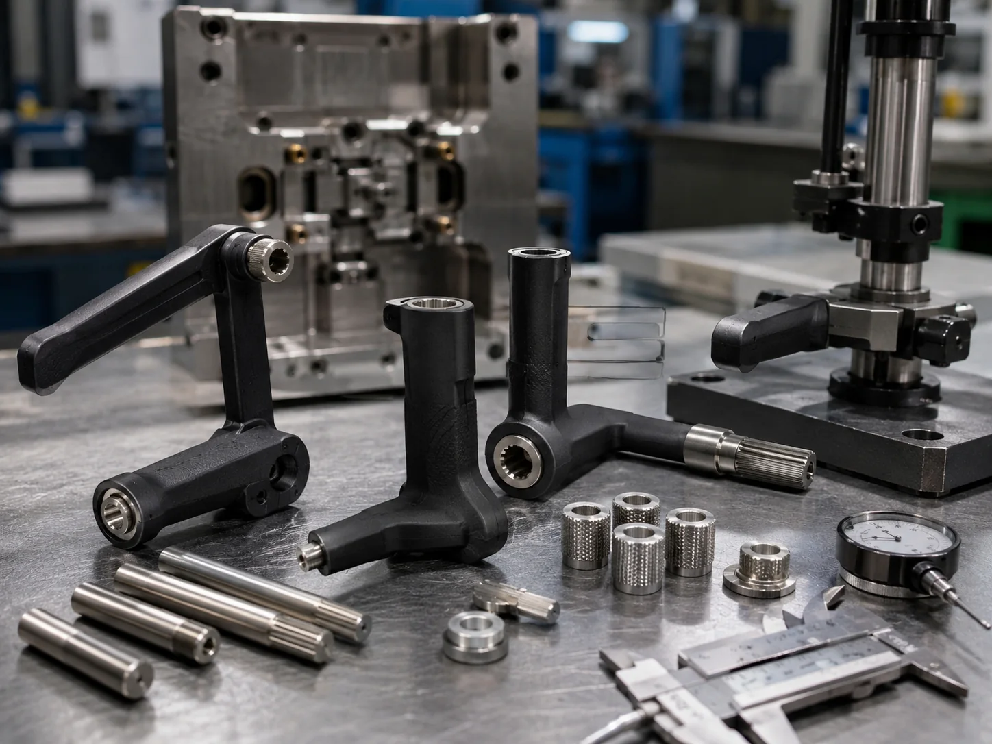
Industrial Control Handle
Material: PA6-GF30
Insert: Steel Shaft
Challenge: High torque requirements in repeated assembly or torque load requirement.
Solution: Deep diamond knurling and pre-heating inserts.
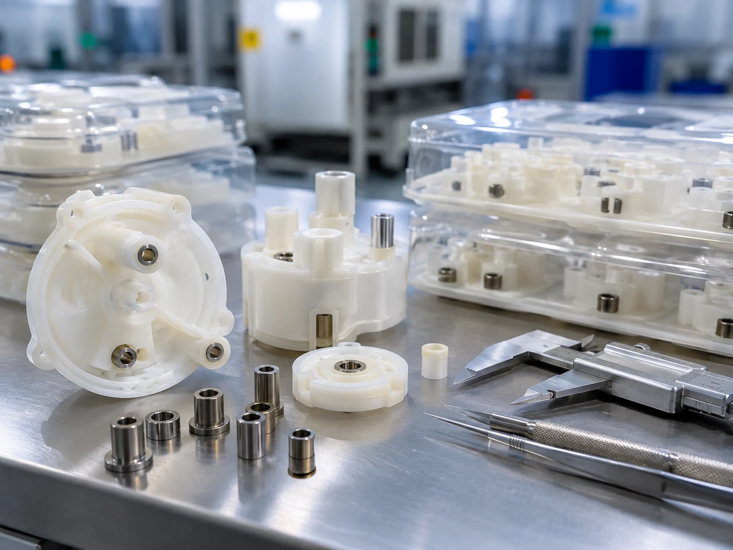
Precision Pump Component
Material: PC or engineering plastic grade based on project requirement
Insert: Stainless Steel Bushing
Challenge: Insert cleanliness, stress cracking risk and stable bushing position
Solution: Insert cleaning review, wall thickness DFM and controlled molding trial.
What Information Should You Send for a Metal Insert Molding Quote?
To provide you with an accurate and fast quotation, please prepare the following details:
Why Work With GBM for Metal Insert Molding?
We don't just build molds; we engineer complete manufacturing solutions.
Mold Design and Injection Molding in One Workflow
GBM supports DFM review, mold design, mold making, T1 trial and injection molding production, reducing communication gaps between tooling and molding.
Insert Positioning Review Before Tooling
We review insert tolerance, locating method, core pin fit, gate direction and mold shut-off areas before cutting steel.
Manual, Fixture-Assisted and Automated Loading Options
Different loading methods can be reviewed according to annual volume, part value, insert quantity and cost target.
Thread Gauge and Visual Flash Inspection
For threaded insert parts, Go/No-Go thread gauge checks and flash inspection can be arranged according to the inspection plan.
Pull-Out and Torque Review Available
For load-bearing insert parts, GBM can support sample review for pull-out and torque-out performance when the requirement is provided.
Export Mold and Molded Part Support
GBM can support mold export, molded part production, trial feedback, inspection photos, packaging photos and shipment communication.
Frequently Asked Questions
What is metal insert molding?
Is metal insert molding the same as insert molding?
What metals can be used for insert molding?
Is brass suitable for metal insert molding?
What plastics work well with metal inserts?
When should I choose metal insert molding instead of heat staking?
Is metal insert molding stronger than post-installed inserts?
How do you prevent insert movement during molding?
What causes cracking around metal inserts?
How do you prevent plastic flash inside threaded inserts?
What is pull-out strength in metal insert molding?
What is torque-out resistance?
Can GBM support manual and automated insert loading?
What information is needed for a metal insert molding quote?
Can GBM make the mold and produce the insert molded parts?
Send Your Metal Insert Molding Drawings for DFM Review
Our engineering team is ready to analyze your project, identify cost-saving opportunities, and provide a detailed quotation within 24 hours. Let's build something robust together.
Email Us
Annie@gbminjection.comCall or WhatsApp
+86 13632611848Factory Address
Room 101, Jiumo Technology Park, Gangsheng Road, Yabian Village, Shajing Street, Baoan District, Shenzhen City